Table of Contents
- Interpretation errors in industrial ultrasound
- Five signs of a doubtful interpretation
- Ultrasonic transducers and beam selection
- How to select the probe
- Calibration blocks for UT calibration
- ASTM E317-21 and ultrasonic system performance
- What the inspector must control
- Conclusions
- References
- Frequently Asked Questions (FAQs)
In industrial ultrasound, a misinterpreted indication can turn a technically correct inspection into a wrong decision. The selection of ultrasonic transducers, the condition of calibration blocks, proper UT calibration, and periodic system verification determine the reliability of the result. In the field, small deviations in angle, sensitivity, resolution, or reference can alter the A-scan response. This article explains how to identify these sources of error, improve inspection accuracy, and use ASTM E317 as a reference to control ultrasonic system performance.
Interpretation errors in industrial ultrasound
One of the most common problems in industrial ultrasound consists of assuming that every relevant indication directly corresponds to a discontinuity. The equipment shows an acoustic response, but it is up to the inspector to determine its origin. Geometry, roughness, reflector orientation, metallurgical structure, coupling, beam divergence, and electronic setup can produce responses similar to those generated by a real discontinuity.
That is why interpreting an A-scan requires separating three processes: detection, characterization, and evaluation. Detecting a signal merely confirms that acoustic energy returned to the transducer. Characterizing involves establishing position, extent, and probable nature. Evaluating means comparing that information with the applicable procedure and acceptance criteria.
Errors appear when these stages are confused. A high-amplitude indication, for example, does not necessarily represent a large discontinuity. A small reflector correctly oriented relative to the beam can return more energy than an extensive but unfavorably oriented discontinuity.
The reverse problem also occurs. A low-amplitude indication may be discarded as noise when it corresponds to a discontinuity whose orientation produces little reflection toward the ultrasonic transducers.
The first practical step consists of checking the system before altering the interpretation. The inspector should verify:
- Coupling stability.
- Surface condition.
- Transducer (probe) position and indexing.
- Configured range and velocity.
- Reference gain.
- Zero point or wedge delay.
- Frequency and angle used.
- Repeatability of the indication.
This sequence reduces the risk of attempting to solve through gain a problem caused by geometry, coupling, or setup.
Another critical factor is the initial reference. Calibration blocks make it possible to establish known conditions against which to compare system response. However, that reference is only representative when the material, geometry, and reflectors are suitable for the procedure used.
Sonatest specifically points out that the reference block material should correspond to the material being inspected and that the artificial reflector should approximate the type of discontinuity sought. That relationship is fundamental to maintaining inspection accuracy.
Five signs of a doubtful interpretation
During an inspection, five signs warrant checking an indication before evaluating it:
- Changes with small movements of the transducer (probe): may indicate variations in orientation, geometry, or coupling.
- Appears from only one direction: may be related to the orientation of the reflector relative to the beam.
- Coincides with a geometric transition: edges, radii, weld roots, or thickness changes can generate echoes.
- Changes when repeating the coupling: it is advisable to check couplant, pressure, surface, and probe contact.
- Its position does not match the geometry: sound path, angle, velocity, and zero point should be checked.
When faced with these signs, it is not advisable to immediately modify UT calibration or classify the response as a discontinuity. First, the acoustic condition must be checked and, when the procedure allows, repeat the scan from different positions to confirm the behavior of the reflector.
Ultrasonic transducers and beam selection
Ultrasonic transducers constitute the interface between the instrument and the part. Their frequency, element diameter or size, damping, configuration, and angle directly influence resolution, penetration, dead zone, and beam behavior. The following should be considered:
- There is no universal probe.
- A higher frequency generally provides a shorter wavelength and can favor the resolution of small discontinuities, but it also increases attenuation in many materials. A lower frequency usually favors penetration, although it can reduce the ability to separate closely spaced reflectors.
In industrial ultrasound, choosing frequency solely out of habit can generate errors even before starting the scan.
Element dimension also affects the acoustic field. The energy distribution presents near-field and far-field regions, as well as divergence. Therefore, the amplitude of an indication does not depend exclusively on the size of the reflector: it also depends on where it is located relative to the beam.
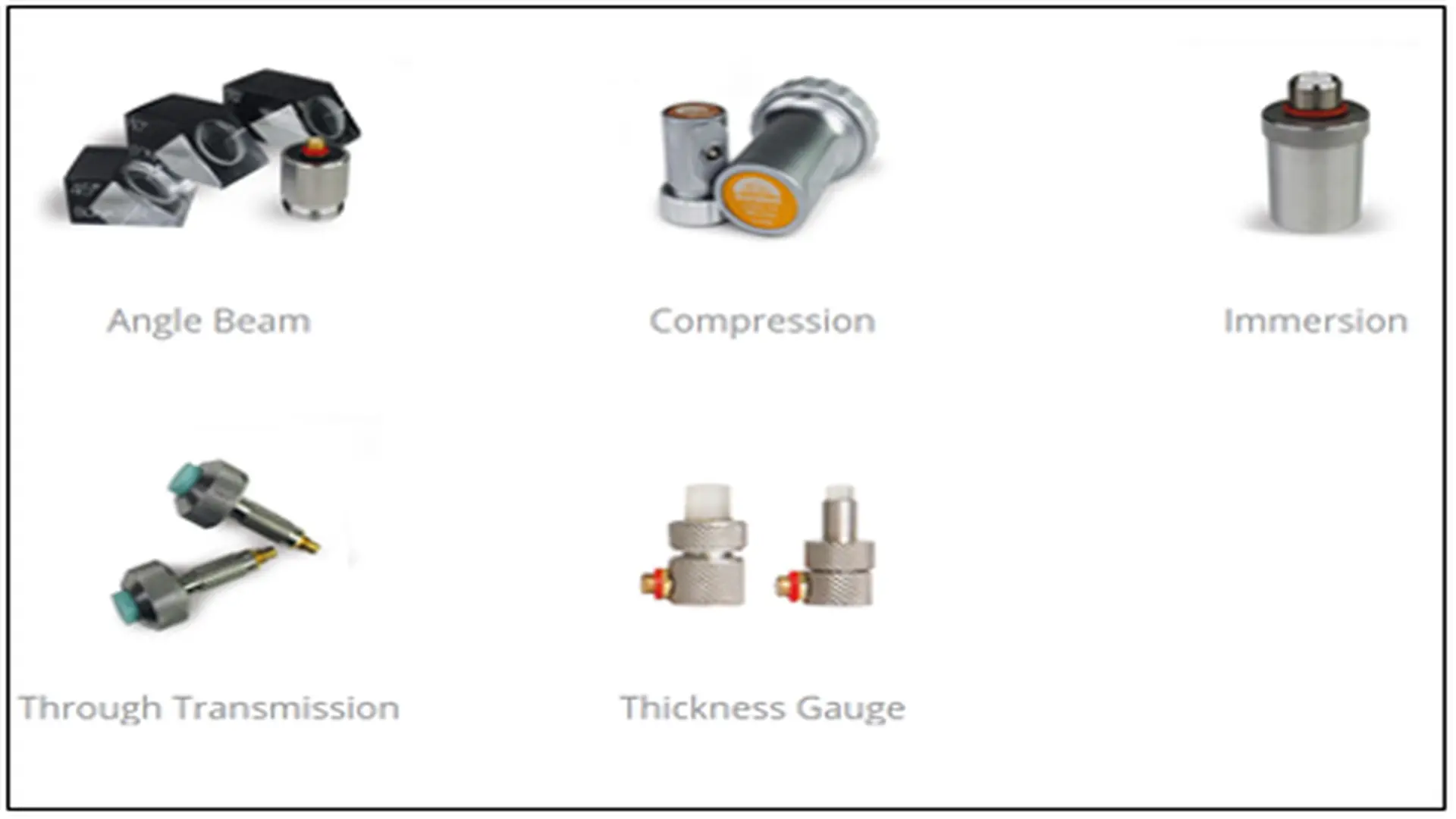
Sonatest manufactures conventional and Phased Array ultrasonic transducers for flaw detection and thickness measurement, with different frequencies, element sizes, and configurations. Their technical catalog covers applications including longitudinal waves, angle beams, immersion, through-transmission, thickness measurement, and TOFD, among others.
How to select the probe
Before selecting ultrasonic transducers, it is advisable to answer five questions:
- Which discontinuity must be detected?
- What is its probable orientation?
- What acoustic path will need to be covered?
- What level of resolution is needed?
- What attenuation and structure does the material present?
In welds, an improper angle can prevent the beam from properly interacting with planar discontinuities. In thick or attenuating materials, a high frequency can also reduce the signal-to-noise ratio. Inspection accuracy requires balancing penetration, resolution, and beam orientation. Furthermore, when replacing a probe, the reference must be re-verified, as even equivalent units can exhibit acoustic differences.
Calibration blocks for UT calibration
Calibration blocks turn abstract system parameters into verifiable acoustic references; these allow checking distance, sensitivity, resolution, angle, exit point, and other characteristics depending on their design. But using just any available block does not guarantee proper UT calibration.
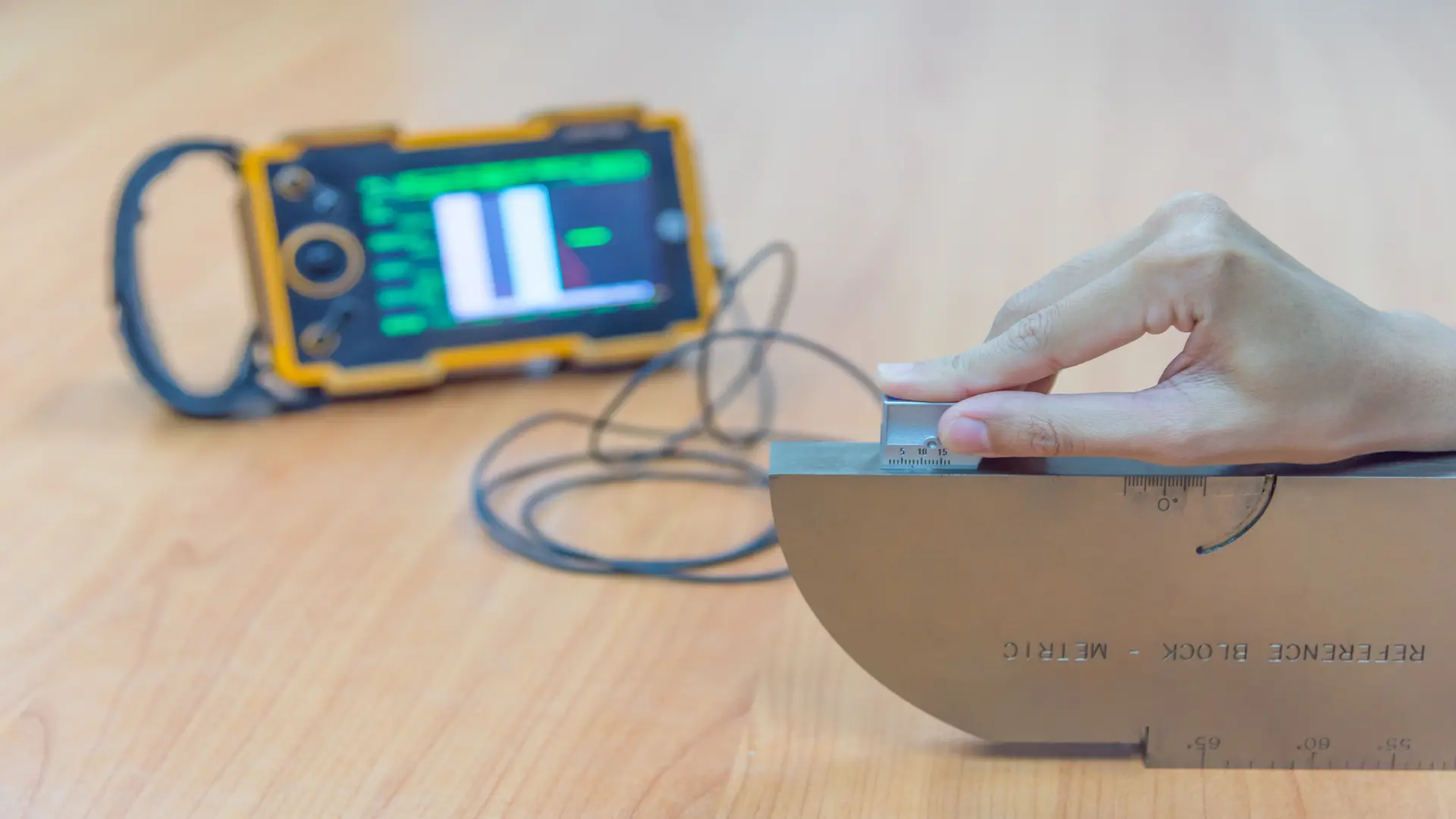
Sonatest offers different types of blocks intended for specific needs: step wedges, standard blocks, DAC, ASME, IIW, ASTM, AWS, and specialized designs. The company highlights that selection depends on the NDT application, the product, and the geometry inspected. In the following image, some of these devices can be appreciated.
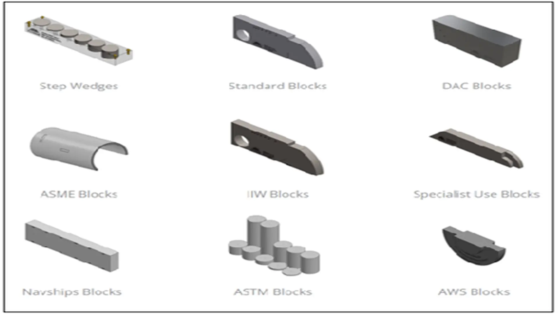
Reference selection must adapt to the acoustic conditions of the inspection. Sonatest offers the V1/A2 block for 0° and angle beam calibrations, the compact V2/A4, and the A5/IOW to verify beam profiles and angles. The A6 block allows evaluating parameters such as frequency, pulse length, dead zone, and resolution. These differences demonstrate that calibration blocks must be selected according to the application and not as generic references.
Material, geometry, and reflector
To achieve inspection accuracy, three variables deserve special attention:
- Material: Differences in acoustic velocity and attenuation between the block and the part can introduce discrepancies. When the code or procedure requires a representative reference, that equivalence must be respected.
- Geometry: A flat surface does not necessarily reproduce the acoustic conditions of a small-diameter pipe. Curvature affects coupling and beam entry.
- Reflector: Side-drilled holes, flat-bottom holes, and notches generate different responses. The choice depends on the method, procedure, and evaluation objective.
An error that goes unnoticed
Suppose the technician sets a reference curve and later changes the probe, cable, or wedge. The instrument retains the curve, but the acoustic system is no longer exactly the same.
Continuing to inspect without verifying the reference can affect inspection accuracy; therefore, any relevant change in the instrument-cable-probe-wedge chain should trigger the verification defined by the procedure.
ASTM E317-21 and ultrasonic system performance
ASTM E317-21 provides procedures for evaluating certain performance characteristics of ultrasonic pulse-echo instruments and systems without requiring additional electronic instrumentation. The practice addresses parameters such as horizontal and vertical linearity, near-surface and far-surface resolution, sensitivity and noise, as well as the accuracy of calibrated gain controls.
The practical value of the practice lies in distinguishing between two concepts that are often confused: system performance evaluation and the calibration or standardization required for a specific inspection. Performance evaluation determines whether certain characteristics of the instrument or system remain within the criteria established for the applicable use, whereas calibration or standardization adjusts the system to the specific conditions of the material, geometry, transducer, and inspection procedure.
The standard states that its procedures do not replace the calibration or standardization required to inspect a particular material. Therefore, evaluation in accordance with this practice does not, by itself, guarantee the validity of the results obtained during a specific inspection.
Furthermore, ASTM E317-21 does not establish general acceptance limits for system performance on its own. Acceptance criteria must be defined according to the requirements of the application, contractual specifications, inspection procedures, or applicable standards and other governing documents.
Consequently, an ultrasonic system may satisfactorily meet a performance evaluation in accordance with ASTM E317-21 and still produce incorrect results if the calibration or standardization required for the specific inspection is performed inadequately. The reliability of the results therefore depends not only on adequate system performance but also on its proper configuration and calibration for the intended application.
What the inspector must control
The inspector’s duties are organized into the following levels:
- Level 1: system performance. Periodically check that instrument, probe, and components maintain stable characteristics. Here ASTM E317 provides a relevant methodological reference.
- Level 2: application setup. Establish range, velocity, sensitivity, zero point, angle, and references required by the procedure.
- Level 3: operational verification. Confirm during the workday that the reference response remains within established tolerances.
If a reference changes after several hours, the technician can investigate coupling, temperature, wedge wear, cable, probe, or instrument before attributing the difference to the component being inspected.
Practical checklist before inspecting
| Verification | What to check | Risk if omitted |
| Applicable procedure | Confirm standard, code, and authorized technique | Inspection out of criteria |
| UT equipment | Identification, condition, and configuration | Non-traceable results |
| Cable and connectors | Physical integrity and signal stability | Loss or fluctuation of amplitude |
| Transducer | Frequency, angle, model, and condition | Poor reflector coverage |
| Wedge | Wear, coupling, and exit point | Error in path or position |
| Calibration blocks | Identification, material, and condition | Incorrect acoustic reference |
| Acoustic velocity | Correct value according to material | Distance or thickness error |
| Range | Suitable window for sound path | Reflectors off-screen |
| Zero point | Correct system adjustment | Localization error |
| Sensitivity | Established reference level | Overestimation or underestimation |
| Resolution | Ability to separate indications | Loss of closely spaced discontinuities |
| UT calibration | Confirm stability before inspecting | Reduced inspection accuracy |
| Periodic verification | Repeat according to procedure | Undetected drift |
| Record | Document changes and checks | Lack of traceability |
During work, checking must be repeated with the periodicity indicated by the procedure and after any event that could modify the system.
Combining this discipline with verifications based on ASTM E317 reduces the probability of an instrumental deviation ending up as an interpretation error.
Conclusions
Reducing errors in industrial ultrasound requires controlling the entire measurement chain, not just correctly interpreting the A-scan. The selection of ultrasonic transducers, the proper use of calibration blocks, reproducible UT calibration, and performance verifications based on ASTM E317 strengthen inspection accuracy.
Sonatest’s technical solutions are pertinent precisely because they allow combining probes and references adapted to different applications. The operating principle is simple: when acoustic conditions change, the reference must be verified before trusting the indication again.
References
- ASTM International. (2021). ASTM E317-21: Standard Practice for Evaluating Performance Characteristics of Ultrasonic Pulse-Echo Testing Instruments and Systems without the Use of Electronic Measurement Instruments. ASTM International. https://doi.org/10.1520/E0317-21.
- Sonatest. (2026). Ultrasonic calibration blocks for NDT testing. Sonatest Ltd. https://sonatest.com/products/calibration-blocks.
- Sonatest. (2026). Ultrasonic transducers for NDT & flaw detection. Sonatest Ltd. https://sonatest.com/products/transducers.
- Sonatest. (2026). A6 calibration block. Sonatest Ltd. https://sonatest.com/products/calibration-blocks/standard-blocks/a6-block.
- Sonatest. (2026). ASME V T-434.2.1 Plate. Sonatest Ltd. https://sonatest.com/products/calibration-blocks/asme-blocks/asme-plate
Frequently Asked Questions (FAQs)
Why doesn’t a high signal mean a large defect?
Because amplitude depends on the size, orientation, and position of the reflector, in addition to frequency, acoustic path, and beam characteristics. In industrial ultrasound, amplitude and size do not maintain a universal direct relationship.
When should transducers be changed?
Ultrasonic transducers should be retired or evaluated when they exhibit wear, loss of sensitivity, physical damage, unstable behavior, or results outside established verifications. The definitive criterion must come from the inspection procedure and the manufacturer.
Which block should be used to calibrate UT?
Calibration blocks must be selected according to method, material, geometry, thickness, type of reflector, and applicable standard. Using an inappropriate reference can generate a reproducible response that is unrepresentative of the actual component.
Does ASTM E317 establish acceptance criteria?
No. ASTM E317 describes procedures for evaluating system performance characteristics, but it does not establish universal acceptance limits; these must be defined by the applicable controlling documents or parties.
How can UT inspection accuracy be improved?
Inspection accuracy improves by correctly selecting the probe, using representative references, periodically verifying the system, and documenting any changes that could affect acoustic response.