Table of Contents
- Acquisition limits in ultrasonic NDT systems
- Practical throughput calculation
- Bottleneck diagnosis
- OEM electronics for fast ultrasonic acquisition
- How to integrate with TPAC and AOS
- Phased array, FMC/TFM, and multichannel acquisition
- Parallelism versus multiplexing
- Complete data or processed results
- Ultrasonic integration in automated systems
- Acceptance test in six steps
- Applicable standards and traceability
- Common errors when accelerating inspection
- Conclusions
- References
- Frequently asked questions (FAQs)
An inspection line can move the scanner faster than its electronics can record each echo. The result is not always an alarm: uncovered bands, duplicated positions, or incomplete images that appear valid may occur. High-speed data acquisition must resolve this difference without sacrificing amplitude, time of flight, or traceability. This guide shows how to calculate the required data throughput, locate the bottleneck, select OEM electronics, and verify performance with a reproducible test.
Acquisition limits in ultrasonic NDT systems
The performance of ultrasonic NDT equipment depends on triggering, propagation, reception, digitization, encoder, transfer, and storage.
A high-speed data acquisition system is sized from the procedure. The analysis considers encoder step, sound path, channels, laws, A-scan length, and format. These requirements are translated into cycles per second and useful throughput. Nominal Ethernet bandwidth does not equal sustained ultrasonic data throughput once headers, control, and writing are taken into account.
Practical throughput calculation
The data volume depends on four variables: positions recorded per second, A-scans generated at each position, samples per A-scan, and bytes used per sample.
Gross throughput = cycles/s × A-scans/cycle × samples/A-scan × bytes/sample
For example, a crawler moving at 400 mm/s and recording data every 0.5 mm must perform 800 cycles per second: 400 mm/s ÷ 0.5 mm = 800 cycles/s
If 64 A-scans are captured in each cycle, with 2,000 samples and 2 bytes per sample, the throughput reaches:
800 × 64 × 2,000 × 2 = 204.8 MB/s
This means that a high-speed data acquisition card capable of transferring only 100 MB/s would not be able to retain all the information. The system would have to reduce the crawler speed, reduce the data through local processing, or incorporate an interface with greater capacity.
In an automated ultrasonic test, the calculation must also consider acceleration, deceleration, and motion variations. Encoder-triggered acquisition maintains a constant distance between measurements. In contrast, time-based triggering alone can leave unrecorded areas when the speed changes. For this reason, it is advisable to incorporate a 20% to 30% capacity margin over the calculated throughput.
Bottleneck diagnosis
The diagnosis starts with a representative acquisition that records requested and effective PRF, frame loss, CPU/GPU utilization, memory, network, disk queue, and temperature. High-speed data acquisition requires a test conducted over a full shift or an equivalent time window. A five-minute demonstration will not reveal heating, memory fragmentation, or storage degradation.
Reducing one variable at a time makes it possible to isolate the cause. If shortening the A-scan eliminates losses, the analysis focuses on transfer or memory. If reducing the number of channels corrects the image, the candidates are parallelism or processing. A position shift directs the review toward the encoder and synchronization. This avoids replacing ultrasonic NDT equipment because of a PC failure.
OEM electronics for fast ultrasonic acquisition
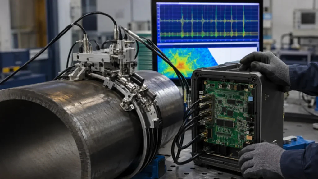
OEM electronics integrate pulsers, receivers, digitization, and control into a scanner, robot, or instrument. A high-speed data acquisition card reduces development compared with designing the entire chain from scratch. The decision should start with the application, not with the maximum number of channels.
For corrosion mapping, spatial step, coverage, and continuity are important; for composites, transmission and parallel channels; for welds, focal laws, dynamic range, and synchronization; for FMC/TFM, data volume and computing capacity. Oversizing the electronics generates more heat, storage requirements, and complexity without necessarily improving the probability of detection.
Minimum specification for the supplier
The proposal specification should include:
- Active, parallel, and multiplexed channels.
- Pulse-echo, pitch-catch, or transmission modes.
- Pulse, PRF, bandwidth, and dynamic range.
- Sampling rate, resolution, and A-scan length.
- Continuous useful throughput and allowable latency.
- Encoders, synchronization, timestamps, and I/O.
- SDK, programming languages, operating systems, and drivers.
- Power consumption, heat dissipation, and environmental conditions.
- Data retained for auditing.
This list turns the purchase of a high-speed data acquisition card into a requirements verification process. The evaluation covers compatibility, code examples, support, and mechanical files. The SDK must detect overflows and associate each A-scan with position and configuration.
How to integrate with TPAC and AOS
TPAC (The Phased Array Company) provides phased-array, multichannel, FMC/TFM, and automation solutions. For manufacturers, its collaboration with AOS provides configurable bare-board modules. This is useful when high-speed data acquisition needs to be integrated into an in-house product rather than added as an external instrument.
AOS publishes for OEM-PA Max up to 64/256 channels, 100 MHz sampling, 10 Gb Ethernet, and up to 1 GB/s useful throughput per unit. It specifies encoders, I/O, and an SDK for several programming languages. This is useful for preselecting a high-speed data acquisition system, but it must be confirmed with the actual PC and software.
The inquiry to TPAC should include cycles, probes, modes, speed, sound path, and environmental conditions. Its contribution focuses on architecture and integration: purchasing a platform, adapting a solution, or incorporating a high-speed data acquisition card through AOS.
Phased array, FMC/TFM, and multichannel acquisition
In a phased-array ultrasonic test, multiple elements emit with delays to produce focal laws. FMC records transmit-receive combinations for TFM reconstruction. With 64 elements, a single position generates thousands of A-scans; a PAUT architecture can become saturated when FMC is activated.
Fast electronics do not eliminate propagation time either. The next pulse must wait long enough to avoid persistent echoes and range ambiguity. In thick or highly attenuating components, the listening window restricts the PRF. The maximum sound path determines how many events can actually fit per second.
Parallelism versus multiplexing
Multiplexing activates groups of channels sequentially and can reduce cost, size, and power consumption. Parallelism captures simultaneous channels and increases productivity in transmission, arrays, or FMC. The decision compares the number of required events with the available cycles. A high-speed data acquisition card with a large number of multiplexed channels is not equivalent to another with the same number of parallel channels.
Example: if a position requires 64 emissions and the motion requires 800 positions/s, the electronics must execute 51,200 emissions/s before considering time of flight. If the maximum sustainable rate is 20,000, the phased-array ultrasonic test must reduce speed, change the capture strategy, or increase parallelism. The comparison should use effective PRF for the configuration, not the pulser’s advertised maximum.
Complete data or processed results
Saving gate amplitudes reduces traffic but limits reprocessing. Retaining complete A-scans allows auditing, modifying TFM, or applying new algorithms. Ultrasonic NDT equipment intended for critical components must define which file constitutes primary evidence, its structure, metadata, and retention period. This decision determines network, memory, and storage requirements.
A hybrid strategy processes data for visualization while retaining complete data in regions of interest. The high-speed data acquisition system must flag discarded data; a continuous image does not demonstrate complete recording. Counters, alarms, and events support data integrity.
Ultrasonic integration in automated systems
In an automated ultrasonic test, position must remain linked to the signal. The encoder defines when to acquire; timestamps allow events to be ordered; the controller coordinates motion, coupling, and safe shutdown. If these clocks do not share a common reference, increasing speed amplifies registration errors even when the network remains available.
The integration must account for abnormal states such as network disconnection, encoder pulse loss, memory saturation, full disk, and overtemperature. Under these conditions, the system must stop, issue an alert, or mark the affected area. Continuing silently is an unacceptable failure mode for industrial inspection.
Acceptance test in six steps
- The configuration reproduces the channels, laws, sampling rate, and A-scan of the worst-case condition.
- The reference documents amplitude, time of flight, and noise on a test block.
- The scanner operates at minimum speed to establish the reference.
- The speed is increased to the target while losses are recorded.
- Sustained operation allows network, memory, and temperature to be monitored.
- The block is scanned again to compare coverage, position, and repeatability.
The criterion should require zero lost frames, spatial step within tolerance, and a response comparable to the slow reference. If the automated ultrasonic test misses an indication when speed is increased, the cause may be acoustic, electronic, mechanical, or algorithmic. Compensating for losses solely by smoothing the image is not an acceptable solution.
Applicable standards and traceability
ISO 16810:2024 establishes general principles and points out additional verifications for arrays. ISO 18563-1:2022 addresses phased-array instruments; ISO 18563-3:2024 addresses the complete system. They provide a framework for the acceptance of ultrasonic NDT equipment without replacing the applicable code.
ASTM E2491-23 provides guidance for evaluating instruments and systems. In a phased-array ultrasonic test, the documentation covers equipment, firmware, probe, wedge, laws, filters, reference block, tolerances, and periodicity. Changing the card or software may require reevaluation.
Common errors when accelerating inspection
- Comparing only MB/s and omitting sustained throughput.
- Confusing available channels with parallel channels.
- Calculating PRF without considering time of flight.
- Using time-based triggering where an encoder is required.
- Validating for minutes and producing for hours.
- Saving only images without ultrasonic evidence.
- Ignoring heat dissipation and SDK maintenance.
Avoiding these errors protects data integrity and the return on integration. The best solution is not always the fastest, but the one that meets coverage, signal quality, traceability, and productivity requirements under repeatable conditions.
Conclusions
High-speed data acquisition begins with the procedure and ends with a sustained field test. Calculating cycles, A-scans, and bytes makes it possible to identify the limit before purchasing hardware. TPAC can support the ultrasonic architecture and, through AOS, facilitate bare-board OEM electronics for integrated products. However, every figure must be validated with the actual probe, PC, software, encoder, and loads. ISO 16810, ISO 18563, and ASTM E2491 provide verification criteria. The practical objective is to increase coverage per shift without losing signals, position, or technical evidence.
References
- Advanced OEM Solutions. (2022). OEM-PA Max: Ultra high speed PAUT & FMC/TFM.
- ASTM International. (2023). ASTM E2491-23: Standard guide for evaluating performance characteristics of phased-array ultrasonic testing instruments and systems.
- International Organization for Standardization. (2022). ISO 18563-1:2022: Non-destructive testing, Characterization and verification of ultrasonic phased array equipment, Part 1: Instruments.
- International Organization for Standardization. (2024a). ISO 16810:2024: Non-destructive testing, Ultrasonic testing. General principles.
- International Organization for Standardization. (2024b). ISO 18563-3:2024: Non-destructive testing, Characterization and verification of ultrasonic phased array equipment, Part 3: Complete systems.
- TPAC. (2024). Global specialist in ultrasonic NDT solutions. https://thephasedarraycompany.com/wp-content/uploads/2024/07/TPAC_BROCHURE_2024-05.pdf
Frequently asked questions (FAQs)
How do I know if the limit is in the electronics?
Varying the A-scan, channels, or PRF independently shows when the losses disappear. If the network and disk become saturated before the pulser, the limit is not in the acoustics. A high-speed data acquisition system must be measured as a complete chain.
How much margin should the calculated throughput have?
A margin of 20% to 30% over the measured worst case covers headers, peaks, and environmental variations. The platform should not operate continuously at the nominal limit of the interface.
When is an OEM bare-board card appropriate?
When the manufacturer needs to incorporate ultrasound into its own instrument, robot, or scanner and control the software, connectors, and form factor. A high-speed data acquisition card reduces development time, but it requires mechanical, thermal, and integration engineering.
Does FMC always require higher speed than PAUT?
It generally generates more A-scans per position because it records transmit-receive combinations. The phased-array ultrasonic test should be compared with FMC using the same coverage, signal length, resolution, and mechanical speed.
How do I validate a fast automated inspection?
Validation compares a test coupon with known reflectors at slow and target speeds, maintains the load during simulated production, and checks losses, amplitude, position, and repeatability. The automated ultrasonic test must fail in a visible and traceable manner.
Does verifying the card certify the complete system?
No. Acceptance must include the electronics, probe, wedge, cables, scanner, encoder, software, and procedure. The complete assembly is validated in the configuration that will perform the inspection.