Table of Contents
Industrial facilities incorporating cathodic protection systems require electrical isolation to be maintained between different sections of a pipeline, tank, or equipment, but they also require overvoltage protection capable of controlling the effects of electrical faults and lightning strikes. This condition becomes particularly important in hazardous locations, where an electrical breakdown or flashover may create an additional ignition hazard.
Isolation joints used in cathodic protection systems constitute a particularly vulnerable point. Although they allow the potential required for corrosion control to be maintained, their insulation may be subjected to high potential differences during transient events. Overvoltage protection devices can limit this voltage and provide a conductive path around the joint when the event occurs.
Overvoltages caused by AC faults and lightning strikes
An alternating-current (AC) fault or lightning strike can cause a rapid increase in the potential difference between the two sides of an insulating joint. If the voltage exceeds the dielectric withstand capability of the insulation, an electrical arc may develop, damaging the joint and creating a hazardous condition.
Dairyland Electrical Industries develops robust electronic technologies that provide electrical safety, reliability, and corrosion protection for critical infrastructure. As a pioneer in decouplers and overvoltage protectors, the company has established itself as a reference in the oil and gas, power, transportation, and marine sectors.
Dairyland protectors use solid-state technology to provide DC isolation during normal operation and conduct when the voltage reaches the specified threshold. These devices are designed to withstand currents associated with AC faults and lightning strikes. The manufacturer specifies impulse current capabilities of up to 100 kA, depending on the configuration and applicable standard.
OVP protectors for isolation joints
Protection must be installed taking into account both the electrical characteristics of the device and its proximity to the joint being protected. During high-frequency events, conductor inductance can generate an additional potential difference; therefore, reducing connection lead length helps improve protection performance.
In cathodic protection systems, the objective is to maintain the DC isolation required by the system while simultaneously providing a low-impedance path during an overvoltage event. Dairyland specifically identifies isolation joint protection as one of the primary applications of its OVP product line.
OVP and OVP2 according to area classification
Device selection must correspond to the hazardous area classification and the electrical conditions of the installation. The OVP is designed for Class I, Division 1 and Division 2 applications, and for Zone 1 under international classification systems. The OVP2 is intended for Class I, Division 2 and Zone 2 applications, as well as ordinary or non-classified locations.
This distinction is relevant in facilities where hydrocarbons, flammable gases, or vapors are present. Selection should not be based solely on the system voltage level: the area classification, substance group, available fault current, impulse level, and specific installation conditions must also be reviewed.
Protection of isolation joints in cathodic protection systems
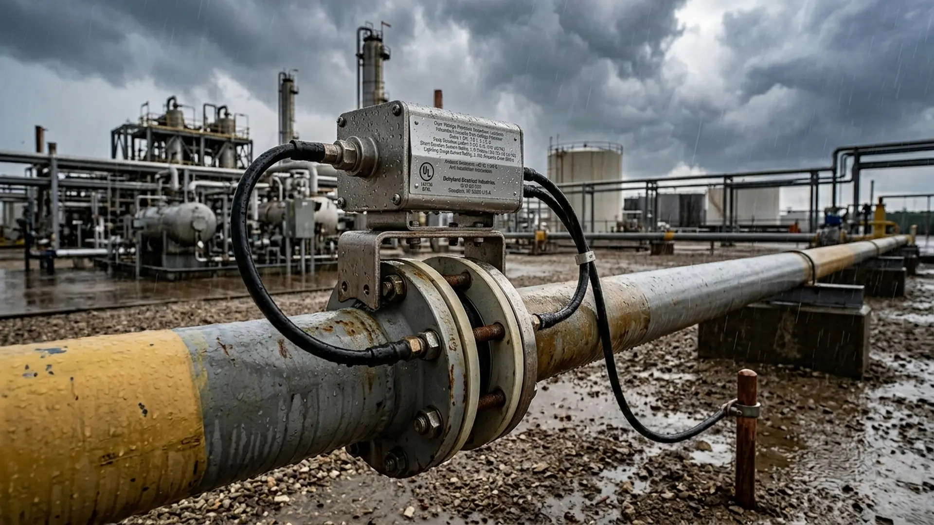
Isolation joints provide electrical isolation between different sections of a pipeline and maintain appropriate voltage levels for the cathodic protection (CP) system. However, they are susceptible to damage from overvoltages caused by lightning strikes or AC faults.
During these events, a dangerous potential difference may develop across the joint, posing a personnel hazard and potentially causing progressive deterioration and, ultimately, failure of the electrical insulation. Current may produce an electrical arc across the joint, creating a potential ignition hazard for flammable materials present inside the pipeline. Affected areas must be repaired to restore the required isolation conditions. Such damage may occur along extensive pipeline sections, increasing maintenance costs and the operational demands placed on the facility.
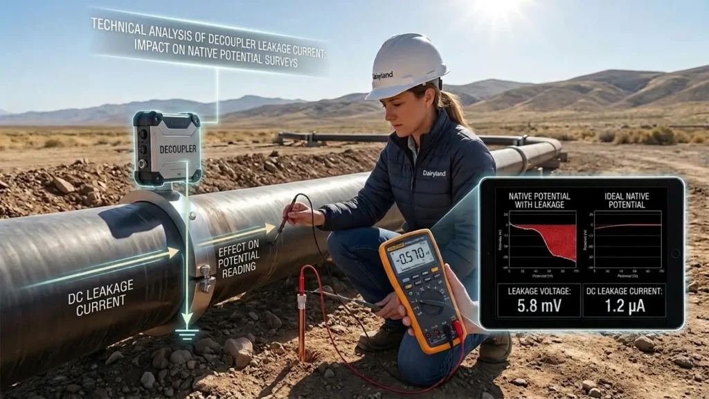
Dairyland provides decouplers and OVP (Over-Voltage Protector) devices designed to provide a low-impedance path in parallel with the insulation when the potential difference reaches the operating threshold. In this way, the device diverts the current associated with the transient event and limits the voltage that can develop across the joint, reducing the likelihood of an electrical arc forming across the insulation.
During normal operation, a Dairyland decoupler or OVP device blocks the direct-current (DC) voltage associated with the pipeline cathodic protection system, maintaining the potential levels required for corrosion control. When an overvoltage exceeds its operating threshold, the device temporarily switches to a conductive state and provides an electrical path around the joint. Once the event has ended, it returns to its blocking state.
In facilities where there is a risk of explosive atmospheres, OVP selection must consider the area classification, applicable certifications, and anticipated electrical conditions. Dairyland offers the OVP for Class I, Division 1 and 2, Groups B, C, and D, and Zone 1 applications; therefore, its use must correspond to the specific classification of the installation.
Integrating overvoltage protection, cathodic protection, and facility safety
Protection of an isolation joint should not be addressed as an independent component of the cathodic protection system. Its performance is affected by the electrical characteristics of the installation, the possibility of AC faults, exposure to lightning strikes, and, particularly, the classification of the area in which it is installed.
During normal operation, the joint must maintain the electrical separation required to control the cathodic protection circuit. However, during an overvoltage event, that same separation may become a point of concentrated potential difference. The function of the protection device is to provide a controlled path for transient current, limiting the voltage that can develop across the joint and reducing the probability of insulation breakdown or electrical arc formation.
For this reason, the specification of an OVP or OVP2 should form part of the overall assessment of the installation. Area classification, voltage level, potential overvoltage sources, available fault current, joint characteristics, and cathodic protection system operating conditions must be considered together. This assessment makes it possible to determine whether the selected device actually meets the service conditions and safety requirements of the installation.
Conclusions
Overvoltage protection is an important component of isolation joint safety. These joints are required to maintain the electrical isolation needed by cathodic protection systems, but they may be subjected to high potential differences during AC faults or lightning strikes. Without adequate protection, an overvoltage can compromise the insulation, produce an electrical arc, and create a hazardous condition, particularly in facilities where flammable gases or vapors may be present.
Area classification must be part of the protection device specification. The selection between OVP and OVP2 should not be based solely on their ability to conduct an overvoltage. Applicable certifications, location classification, system electrical conditions, and foreseeable fault scenarios must be verified. In classified areas, compatibility between the device and the installation environment is a technical requirement that must be considered during the design stage.
Overvoltage protection must be integrated into the cathodic protection design and the facility integrity strategy. The objective is not simply to protect an isolation joint, but to maintain its function within the cathodic protection system during normal operation and control transient conditions that could damage it. Proper device selection makes it possible to address corrosion protection system continuity, insulation integrity, and industrial facility safety as interconnected requirements.
Before specifying an overvoltage protector for an isolation joint, it is necessary to assess the area classification, potential overvoltage sources, and electrical conditions of the system. Incorrect selection can compromise both cathodic protection and facility safety.
References
- Association for Materials Protection and Performance. (2007). Electrical isolation of cathodically protected pipelines (NACE SP0286-2007). AMPP. https://doi.org/10.5006/NACE_SP0286-2007
- Association for Materials Protection and Performance. (2024). Control of external corrosion on underground or submerged metallic piping systems (AMPP SP0169-2024). AMPP.
- American Petroleum Institute. (2023). Classification of locations for electrical installations at petroleum facilities classified as Class I, Division 1 and Division 2 (API Recommended Practice 500) (4th ed.). API.
- American Petroleum Institute. (2018). Classification of locations for electrical installations at petroleum facilities classified as Class I, Zone 0, Zone 1, and Zone 2 (API Recommended Practice 505). API.
- International Electrotechnical Commission. (2020). Explosive atmospheres, Part 10-1: Classification of areas, Explosive gas atmospheres (IEC 60079-10-1:2020). IEC.
- Dairyland Electrical Industries. (2025). OVP2: Rugged over-voltage protection. Dairyland Electrical Industries. https://www.dairyland.com/product/ovp2/