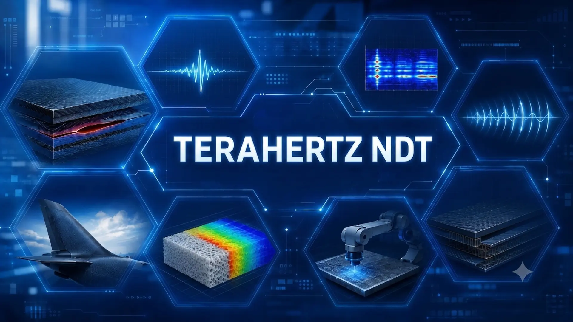
Composite materials reduce weight and resist corrosion, but their layered architecture can hide delaminations, adhesive disbonds, voids, moisture, and impact damage. These discontinuities can degrade load transfer or thermal performance without leaving surface evidence.
Ultrasound, radiography, thermography, and shearography remain core methods. Terahertz NDT incorporates a different contrast: the electromagnetic response of polymers, adhesives, foams, and coatings.
The technique operates non-contact, without couplant, and without ionizing radiation. Its value depends on converting permittivity and optical path changes into validated indications for the material, geometry, and target defect.
What terahertz NDT actually measures
When a terahertz wave strikes an interface between media with different dielectric properties, part of the energy is reflected and another part continues propagating. The time of arrival allows estimating the depth; the amplitude and phase describe the attenuation and delay introduced by the material.
The real part of the complex refractive index relates to the phase velocity, and the imaginary component to the losses. The system does not directly identify a delamination: it registers an electromagnetic perturbation that must be correlated with the component’s architecture and the expected damage.
Materials within the terahertz window
The most favorable candidates are dry, low-conductivity dielectrics: polymers, resins, foams, ceramics, GFRP, and certain aramid composites.
CFRP (Carbon Fiber Reinforced Polymer) requires specific evaluation. Its conductive fibers attenuate and polarize the field; the response changes with fiber fraction, layup, thickness, electric field direction, and frequency.
Metals block transmission. They can act as reflectors under coatings or insulation, but a discontinuity located behind a metal wall remains outside the inspection window. ISO/AWI 26421 recognizes these restrictions and limits CFRP to certain orientations and thicknesses.
Penetration and resolution: different variables
The useful depth is governed by absorption and scattering. In low-loss dielectrics, it can reach from millimeters to centimeters; water, conductive fibers, and heterogeneity reduce that distance.
Lateral resolution depends on wavelength, numerical aperture, and focus. In far-field systems, it is usually on the order of 0.5 mm or greater, although that value does not constitute a universal limit.
Axial resolution depends on bandwidth and the group refractive index. If two interfaces fall within the system’s temporal response, their echoes overlap and cannot be directly separated.
Defects detectable through terahertz imaging
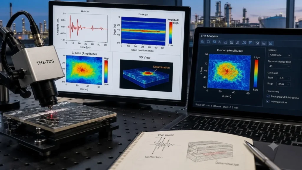
A scanning system records a waveform or frequency response at each coordinate. It then generates B-scans, C-scans, amplitude maps, depth slices, or three-dimensional reconstructions of the interfaces.
In GFRP, THz-TDS has allowed visualizing overlapping delaminations and estimating their depth. A 2026 study combined adaptive fusion and segmentation to integrate defects at different depths, with mean errors below 7% in controlled specimens.
The potential includes adhesive disbonds, air pockets, inclusions, thickness changes, damage in foam cores, and moisture. The response changes with the dielectric contrast, depth, and orientation of the discontinuity.
Why a clear image might be insufficient
The processed image does not necessarily reproduce the exact geometry of the defect. Time windows, deconvolution, interpolation, and filtering can alter the apparent area and contrast.
Multiple reflections can also cause ghost echoes. The procedure must differentiate a physical interface from a repetition caused by the electromagnetic path within a multilayer system.
Moisture has a dual effect: it increases contrast by absorption, but it can block the signal to deeper regions. A highly attenuated zone must not be automatically interpreted as damage extension.
The space shuttle foam precedent
After the Columbia accident, NASA evaluated technologies to locate voids and delaminations in the external tank’s insulating foam. Terahertz imaging and backscatter radiography were selected after blind testing.
NASA’s documentation calls the system terahertz imaging, although it notes that the pulse used was in the millimeter-wave regime, near the lower limit of the terahertz region.
The application demonstrated the value of single-sided access over dielectric insulation with a reflective backing. Performance remained conditioned by the foam, thickness, geometry, discontinuity, and equipment used.
How THZ-TDS spectroscopy works
Time-domain terahertz spectroscopy typically employs ultrashort pulses generated in photoconductive antennas or by optical rectification in nonlinear crystals, via excitation with femtosecond lasers. The detector records the electric field as a function of time.
A Fourier transform obtains amplitude and phase versus frequency, along with information on interfaces, refractive index, and absorption.
Thin layers, scattering, and multiple reflections can overlap echoes. Their separation may require time windows, deconvolution, or propagation models.
From pulse to depth
In transmission, the emitter and receiver are placed on opposite faces. The configuration measures the attenuation and delay through the component, but requires access and alignment on both sides.
In reflection, both elements operate from the same face. Each interface returns part of the energy and generates a response functionally comparable to an electromagnetic pulse-echo.
For a homogeneous layer, with near-normal incidence and separable echoes, thickness can be estimated by:
d = cΔt / 2ng
Where ng is the group refractive index.
What spectral characterization provides
THz-TDS estimates the refractive index and absorption, parameters that can be correlated with density, moisture, or degree of cure through validated references.
The expression “chemical information” requires caution: mixtures, thickness, moisture, and spectral resolution can prevent an unambiguous identification.
In industrial inspection, it is more accurate to speak of dielectric and spectral characterization. Attributing a variation to a chemical change requires demonstrated selectivity and interference control.
From refractive index to density control
A recent quantitative application used time-of-flight THz imaging in reflection to relate the effective refractive index to the density of polypropylene foams. The calibration was built with samples between 70 and 900 kg/m³ placed on a metal plane.
The estimated mean densities showed absolute errors below 10 kg/m³ and percentage errors close to 5%. The pattern of a foam with graded density showed good qualitative and quantitative agreement with X-ray microscopy.
The result is not equivalent to a full three-dimensional tomography: each pixel represents a mean effective density throughout the thickness. Applying the method to other foams requires its own calibration, sufficient penetration, repeatability, and scattering control.
Terahertz NDT versus other ndt methods
Each method responds to a different physical property. The comparison must determine which contrast allows resolving the damage mechanism and the engineering decision.
| Method | Primary contrast | Favorable applications | Dominant limitation |
| Terahertz NDT | Permittivity and optical path | Dielectric layers, GFRP, foams, and coatings | Absorption, conductivity, and penetration |
| Ultrasound | Acoustic impedance and scattering | Thickness, delaminations, and volumetric damage | Coupling, anisotropy, and attenuation |
| Radiography | Attenuation and projected density | Inclusions, porosity, and internal geometry | Ionizing radiation and defect orientation |
| Active thermography | Thermal diffusion | Subsurface disbonds and wide coverage | Depth and thermal excitation |
| Shearography | Surface strain gradient | Disbonds and delaminations in large areas | Controlled loading and lack of direct depth |
Value of the multisensor strategy
Fusion requires correcting the geometry, registering the data in the same coordinate system, and preserving the uncertainty of each technique.
Terahertz provides dielectric contrast; UT, mechanical response; thermography, thermal diffusion; shearography, strain perturbations; and tomography, high-resolution volumetric geometry.
The selection must respond to the damage mechanism and the consequence of a missed detection. Fusion provides value when each sensor reduces a specific uncertainty.
Terahertz NDT and nondestructive testing 5.0
A THz scan forms an x-y-time or x-y-frequency data cube. Reducing it to a colored image eliminates useful information for analysis and traceability.
Automated segmentation requires correcting surface topography, working distance, and instrumental response before comparing signals or maps.
Nondestructive Testing 5.0 describes this integration of sensors, robotics, physical models, and intelligent analysis. They do not constitute a normative classification.
Hardware for automated inspection
The automation of Terahertz NDT depends on integrating the source, the detector, the positioning system, the synchronization, and the signal processing within the same acquisition architecture.
Current platforms incorporate reflection heads, motorized stages, and remote control. In asynchronous optical sampling configurations, the time sweep can be executed without a mechanical delay line, favoring faster acquisition.
Traceability before automatic classification
An auditable system must store the original signal, coordinates, reference, calibration, environmental conditions, algorithm version, and final disposition.
Artificial intelligence can prioritize regions, but it must be validated with external samples and representative variability.
For acceptance decisions, each result must maintain traceability back to the signal, the processing, and the measurement uncertainty.
Standardization and industrial qualification
ISO/AWI 26421 remains under development, at stage 20.00. It covers transmission, reflection, equipment, calibration, analysis, thickness measurement, and defect evaluation in plastics and composites.
ISO/CD 26273 is at stage 30.20 for measuring non-metallic coatings and single layers using terahertz spectroscopy. Conductive materials act as reflectors and cannot be penetrated.
Neither of these documents yet constitutes a published international acceptance standard. Industrial application requires a specific procedure for the component and the target damage.
What a procedure must demonstrate
The qualification must define material, layup, thickness, geometry, surface condition, defect, minimum size, depth, and orientation.
The specimens must include healthy zones and discontinuities representative of the process or service. Artificial inserts with high contrast can overestimate detectability.
The evaluation must quantify repeatability, resolution, false calls, sizing error, environmental sensitivity, and uncertainty. High-consequence applications may require a formal probability of detection study.
Conclusions
Terahertz NDT brings to composite inspection a variable that other methods do not measure in the same way: permittivity and optical path within dielectric materials.
This capability allows evaluating layers, interfaces, foams, coatings, and certain composites without contact, couplant, or ionizing radiation. Conductivity, water, geometry, and overlapping echoes limit its application.
The decisive step is converting the signal into a qualified measurement. When detectability, processing, uncertainty, and correlation with actual damage are documented, Terahertz NDT can support manufacturing control and integrity decisions. A high-contrast image, by itself, does not constitute sufficient technical evidence.
References
- ISO. ISO/AWI 26421 and ISO/CD 26273.
- NASA. Nondestructive Evaluation of Foam Insulation.
- Catapano et al. Foam Density Mapping via THz Imaging.