Table of Contents
- What happens when thermal insulation becomes saturated with moisture?
- What does it mean to dry insulation in situ?
- IVS: Ventilation and drainage as a system
- What did the 97% drainage test demonstrate?
- PTFE Spacer Wrap: Separating insulation from the pipeline
- Field case: Measured drying over seven months
- Applied R&D on wet insulation behavior
- When to dry and when to replace
- From thermal insulation to an integrity decision
- Conclusions
- References
- Frequently Asked Questions (FAQs)
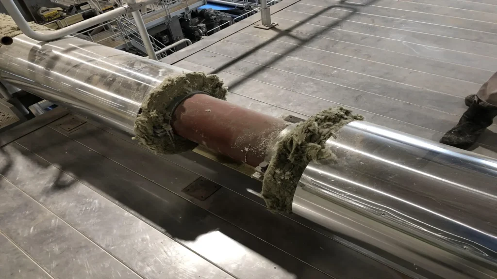
When water enters an insulated system, in most cases the damage begins without evident external signs. In thermal insulation on pipelines, retained moisture reduces thermal performance, prolongs the time the metal remains wet, and promotes conditions associated with corrosion under insulation (CUI).
Removing and replacing all the insulation is necessary when the material loses its function or the substrate requires repair, but it should not always be the first decision. If wet insulation on pipelines retains recoverable conditions, in-situ drying can be supported by ventilation, drainage, and physical separation to remove moisture without automatically dismantling the entire system.
What happens when thermal insulation becomes saturated with moisture?
It is easy to assume that a hot pipeline will eventually dry wet insulation on its own. In reality, heat can mobilize moisture without guaranteeing that it leaves the system. Water near the surface may evaporate, move radially, and condense again when it reaches colder areas.
The study A Hybrid Approach for Effective CUI Management, by Ahmad Raza Khan Rana and Graham Brigham, describes this behavior. Vapor can migrate through the insulation or reach the inner face of the jacketing and return to the liquid state when it reaches its dew point.
Gravity drives the liquid phase toward the bottom of the pipeline. If there is no effective outlet, water can accumulate around the 6 o’clock position and return to the insulation through capillary action. Operating temperature and gravity alone do not guarantee stable drying.
Reducing wetting time is important because it decreases the time during which the insulation and metal surface remain wet. Moving water within the system is not the same as completely removing it from the system.
What does it mean to dry insulation in situ?
Through the in-situ insulation drying process, moisture is removed while the material remains installed. This does not mean indiscriminately perforating the outer cladding or assuming that any wet insulation can be recovered.
For the process to work, there must be a pathway for vapor, space through which air can circulate, and low points through which liquid water can exit. The evacuated moisture must not be allowed to become trapped again in another area.
The condition of the insulation is fundamental. Collapsed, contaminated, or degraded material may require replacement. If the pipeline has wall-thickness loss or damage requiring repair, drying does not replace that intervention.
The decision should answer two questions: Can the insulation be recovered? Is the condition of the metal acceptable? Only then does it make sense to retain the material and specifically address the retained moisture.
IVS: Ventilation and drainage as a system
The Insulation Ventilation System (IVS®) from Integrity Products is a patented technology consisting of Perforated Dimple Wrap™, IVS Vents™, and IVS Drains™. These components work together to create ventilation and drainage pathways that promote the removal of moisture retained within the insulation.
The Perforated Dimple Wrap™ creates an approximately 6 mm air space between the insulation and the metal cladding. Its perforated surface allows moisture and vapor to migrate into this cavity before reaching an exit pathway.
IVS Vents promote airflow and are normally positioned at the 3 and 9 o’clock positions; IVS Drains operate by gravity at the 6 o’clock position. The technical documentation specifies a typical spacing of three meters between these elements, although the final configuration depends on the installation design.
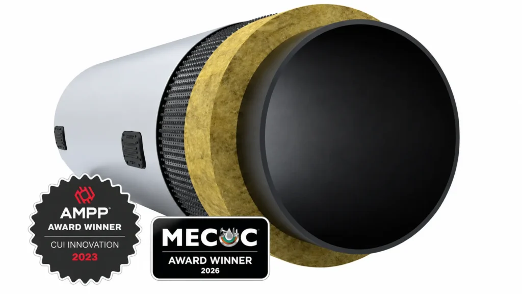
The principle is to allow vapor to reach a ventilated cavity and enable recondensed water to find a low-point drain, avoiding a closed system in which moisture repeatedly changes between the liquid and vapor phases.
The following video shows the arrangement of the PTFE Spacer Wrap and the Insulation Ventilation System (IVS®) on an insulated pipeline, allowing visualization of how separation, ventilation, and drainage are integrated into the system.

What did the 97% drainage test demonstrate?
In the study Moisture Drainage and Stand-Offs Impact on Insulation Wetting, Rana and Brigham experimentally studied how stand-offs and low-point drains affect moisture retention. In the work published in Materials Performance, insulated pipe assemblies received measured quantities of water, after which the amount of liquid removed under each configuration was quantified.
The configurations were also evaluated using moisture-detection imaging. The non-contact insulation system with bottom drains achieved a maximum drainage efficiency of 97% and showed the lowest moisture retention among the alternatives tested.
That 97% should not be presented as guaranteed performance for every installation. It is the result of a specific experimental configuration. Its significance lies in demonstrating the combined effect of two mechanisms: maintaining physical separation and providing an effective outlet at the low point.
After four wetting cycles, the authors also observed a dry pipe surface beneath the non-contact configuration with a perforated liner. The result reinforces a central technical principle: within fibrous insulation, water requires a designed pathway; gravity alone may not be sufficient. Reference.
PTFE Spacer Wrap: Separating insulation from the pipeline
The PTFE Spacer Wrap™ operates at a different interface. While the IVS Perforated Dimple Wrap creates space between the insulation and cladding, the PTFE Spacer Wrap generates approximately 6 mm of separation between the insulation and the process pipeline.
This establishes non-contact insulation. The PTFE wrap forms a barrier between the insulation system and the pipeline, while the separation prevents wet insulation from remaining directly against the metal substrate.
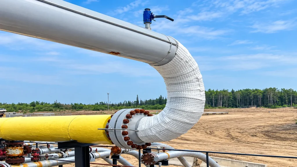
This distinction is important. IVS promotes ventilation and drainage within the insulation package; PTFE Spacer Wrap modifies the interface between the insulation and the pipeline. In multilayer configurations, both principles can work complementarily.
API RP 583, in its third edition published in 2026, addresses design, maintenance, inspection, and mitigation practices related to CUI and CUF. Integrity Products links PTFE Spacer Wrap in its documentation to the leachate barrier concept and IVS to insulation drying wraps; this correspondence is the manufacturer’s technical interpretation, not a specific product approval by API.
Field case: Measured drying over seven months
A case published by Integrity Products concerns a heavy crude oil production facility with recurring saturation. Two insulation renewal projects had already been carried out on sections of a crude emulsion line more than 32 km long, but different areas were found to be wet again.
Instead of initiating another general replacement, the owner tested IVS on selected sections and compared them with conventional sections. Moisture was measured at three depths: adjacent to the pipe surface, at the middle of the insulation, and near its outer circumference. Measurements were repeated every two weeks for seven months.
The technical article reported a significant reduction in moisture at all three depths and near-zero values at locations with IVS. It also documented the formation of icicles at the 6 o’clock position during cold conditions, providing visual evidence that moisture was leaving the system through the lower section.
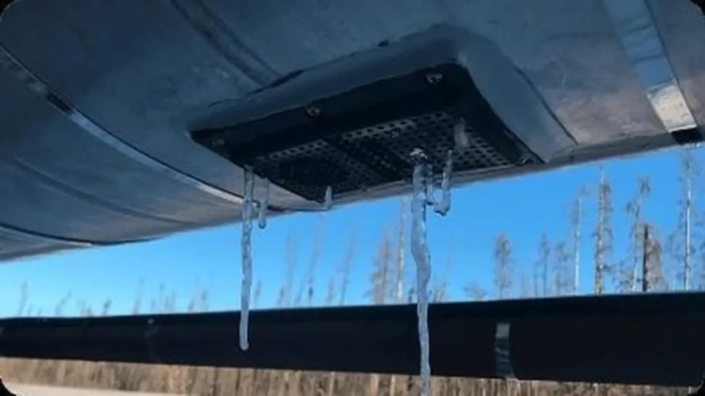
The current case page states that heavily saturated sections reached dry conditions in approximately five to six weeks and reports recovery of thermal performance. These results correspond to the case presented by the company; material, thickness, temperature, geometry, and initial saturation may modify the time required at other installations.
Applied R&D on wet insulation behavior
Integrity Products maintains an R&D platform for testing materials and systems under controlled conditions. Its capabilities include simulations of corrosion under insulation (CUI) and evaluations aimed at studying how moisture, temperature, and materials affect the behavior of insulation systems.
Its laboratory also provides insulation testing up to 450 °C, heat-flow measurement between −70 and 120 °C, and FLIR thermography. These capabilities make it possible to analyze both thermal performance and conditions that may promote CUI, aspects directly related to the development of ventilation, drainage, and non-contact insulation solutions.
In 2026, Ahmad Raza Khan Rana and Graham Brigham received the Oladis Troconis de Rincón Field Applied Technology Award from AMPP. Integrity Products associates this recognition with the development of multilayer insulation systems that combine separation, ventilation, and drainage to reduce moisture retention and conditions that promote CUI.
When to dry and when to replace
The first condition for considering drying is that the insulation retain sufficient integrity to continue performing its function. If it is degraded, contaminated, compacted, or has irreversibly lost its properties, retaining it may simply postpone the problem.
The second is knowing the condition of the metal. If CUI or wall-thickness loss is suspected, CUI inspection techniques should be applied before making a decision. Drying an area does not restore lost metal or eliminate a required repair.
The third condition is verifying the result. The IVS case used periodic measurements at different depths over several months; this criterion is more robust than assuming that a dry exterior surface represents the condition throughout the insulation thickness.
When these conditions are met, drying can be an alternative to indiscriminate replacement. The potential benefit lies in retaining recoverable material and reducing intervention, waste, and work time, provided that the condition of the asset remains technically controlled.
From thermal insulation to an integrity decision
Thermal insulation on pipelines should not be evaluated solely by its ability to maintain temperature. When moisture is present, it is also important to consider how long the insulation remains wet, where water accumulates, and whether the design provides a controlled pathway for its removal.
IVS addresses ventilation and drainage; PTFE Spacer Wrap modifies the contact between insulation and pipeline. The studies published by Rana and Brigham explain why separation and low-point drainage can reduce retention, while the field case demonstrates that in-situ drying of insulation can be monitored through measurements during operation.
Do you need to assess whether ventilation, drainage, or non-contact insulation can be applied to an existing installation? Connect with Integrity Products & Supplies Inc through Inspenet Corporate to learn about its capabilities and establish technical contact with the company.
Conclusions
The decision to dry or replace an insulation system should not be based solely on the presence of water. It is necessary to evaluate the condition of the insulation material, the metal, and the system’s ability to evacuate moisture in a controlled manner. When these conditions are favorable, thermal insulation on pipelines can recover part of its functionality through measures such as ventilation, drainage, and physical separation of the affected areas.
The value of in-situ drying lies in retaining those components that can still perform their function, provided that retained moisture can be removed and the risk can be prevented from being transferred to a later stage.
References
- American Petroleum Institute. API RP 583 , Corrosion Under Insulation and Fireproofing. Third Edition, 2026.
- Rana, A. R. K.; Brigham, G. A Hybrid Approach for Effective CUI Management. Inspectioneering Journal, 2023.
- Rana, A. R. K.; Brigham, G. Moisture Drainage and Stand-Offs Impact on Insulation Wetting. Materials Performance, 2020.
- Integrity Products & Supplies Inc. In Situ Drying of Moisture Saturated Thermal Insulations. 2026.
- Integrity Products & Supplies Inc. Research and Development, Engineering Validation Through Controlled Testing.
Frequently Asked Questions (FAQs)
Can a hot pipeline dry wet insulation by itself?
Not necessarily. Moisture may evaporate near the pipeline and condense again in colder areas.
What is the difference between IVS and PTFE Spacer Wrap?
IVS creates ventilation and drainage within the insulation system; PTFE Spacer Wrap creates separation between the insulation and the pipeline.
How long does IVS take to dry saturated insulation?
Integrity Products reported five to six weeks in a field case. The required time depends on the conditions of each installation.
Does drying the insulation eliminate existing CUI?
No. Drying reduces moisture and wetting time; any existing corrosion must be inspected and evaluated separately.