Table of Contents
- Overpressure risks in fluid transfer
- Conditions that elevate pressure
- Diagnosis of conditions before selecting
- Industrial valves for flow control
- Valve selection according to function
- Sizing and control to avoid instability
- Integrated selection with IOCS SrL
- Shutoff valves in loading and unloading
- Operational sequence and emergency shutdown
- Control does not equal relief
- Verification, maintenance, and indicators
- Conclusion
- References
- Frequently Asked Questions (FAQs)
A seconds-long maneuver can unleash an overpressure capable of rupturing pipes, hoses, or gaskets. In fluid transfer systems, correctly selecting and operating flow control valves reduces transients, leaks, and shutdowns. This analysis explains how to recognize overpressures, compare industrial valve types, and combine control, isolation, and overpressure protection from engineering to maintenance.
Overpressure risks in fluid transfer
Overpressure occurs when a component’s design limit is exceeded. The analysis must include static pressure, pump shutoff head, elevation, thermal expansion, and transients. In fluid transfer systems, the weak link can be a hose, gasket, quick coupling, or lower-class pipe section.
Conditions that elevate pressure
Rapid closure transforms the kinetic energy of the liquid into a pressure wave. Water hammer depends on velocity, density, elasticity, and maneuver time. Poorly programmed flow control valves can cause it, as can abrupt pump changes, check valve slam, or line blockage.
Liquid trapped between two valves can build up pressure as it heats up, even without pumps operating. Overpressure protection must consider thermal expansion, fire, trapped gas, vaporization, and incorrect connections. API 521 guides relief and depressurization analysis in petroleum, petrochemical, gas, and LNG facilities (API, 2020).
Diagnosis of conditions before selecting
First, the hydraulic profile between source and receiver is built, including flow rates, pressure, temperature, properties, elevations, diameters, losses, pump curves, and valve positions. The model must represent two-phase, viscous, corrosive, or solid-laden fluids, and flow control valves are sized using these data, not just line diameter.
The scenario matrix records cause, maximum pressure, available time, safeguard, and consequence. The transient study estimates the wave, evaluates closing times, and checks accumulators or recirculation; thus defining where overpressure protection requires relief and where it is advisable to modify the sequence.
Allowable pressure must be verified for each component and temperature. ASME B16.34 covers, among other aspects, pressure-temperature ratings, materials, testing, and marking of new valves (ASME, 2025). This verification prevents installing industrial valve types with compatible materials but inadequate pressure class, end connections, or testing for the service.
Industrial valves for flow control
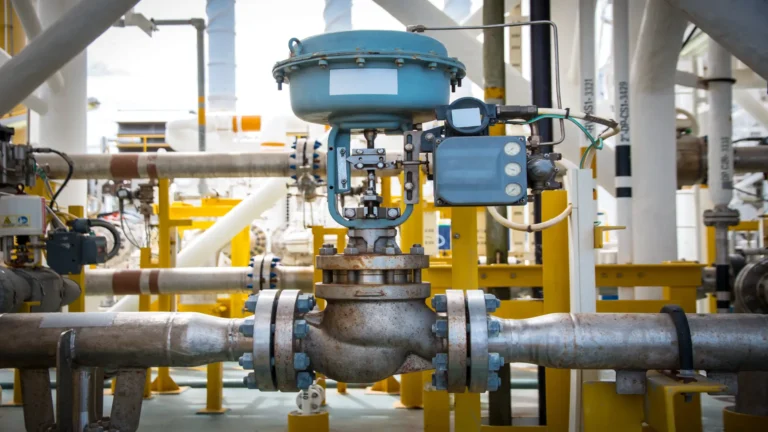
Controlling, isolating, preventing backflow, and relieving are different functions. Flow control valves modulate flow or pressure; isolation valves open or close; check valves prevent backflow; relief valves discharge when reaching their setpoint. The design must assign each function and avoid relying on a single barrier in fluid transfer systems.
Valve selection according to function
The globe throttling valve offers predictable control, although it generates higher pressure drop. The butterfly valve is compact for large diameters; its performance depends on the disc, seat, and opening degree. Among industrial valve types, both can modulate if the manufacturer validates cavitation, noise, velocity, and torque.
The ball valve offers low pressure drop and rapid closure for isolation. Throttling with a conventional design can erode seats or concentrate velocity. Segmented or characterized ball flow control valves are different. Selection considers flow coefficient, rangeability, inherent curve, and valve authority.
The gate valve is normally used for full opening or closing; working partially open can cause vibration and erosion, while the check valve function requires analyzing minimum velocity, orientation, differential pressure, and disc dynamics. Slow closure can permit backflow; abrupt closure can amplify transients. Comparing industrial valve types implies studying the system, not choosing at random or solely based on costs.
Sizing and control to avoid instability
To size flow control valves, flow rate, upstream and downstream pressure, density, vapor pressure, temperature, and flow regime are reviewed. In liquids, cavitation or flashing must be checked; in gases, choked flow, noise, and velocity. The result defines size, trim, actuator, and characteristic.
Stroke time is also a safety variable. Closing quickly reduces the inventory released during a leak, but can increase water hammer. Closing slowly decreases the transient, although it prolongs transfer during an emergency. In fluid transfer systems, this compromise is resolved through simulation, two-speed valves, control ramps, or stepped closure, and is subsequently validated through functional testing.
Integrated selection with IOCS SrL
IOCS SrL supplies ball, butterfly, check, gate, and globe valves, in addition to Y-strainers, spools, flanges, gaskets, couplings, and hoses. This offering facilitates integrating various industrial valve types in loading stations.
Specifications must consider fluid compatibility, pressure class, connections, torque, actuation, testing, and spare parts. In fluid transfer systems, coordinating these components reduces incompatibilities during assembly or replacement.
IOCS also offers assistance in installation, commissioning, maintenance, and turnarounds. This capability can support the integration of flow control valves, although responsible engineering must approve sizing and overpressure protection.
Shutoff valves in loading and unloading
Safe transfer requires local, remote, and emergency isolation consistent with risk. Manual valves isolate equipment for operation and maintenance; motorized valves enable sequencing; emergency shutdown (ESD) valves isolate under dangerous conditions.
Operational sequence and emergency shutdown
Before starting, alignment, available receiver capacity, required vent openings, hose condition, communications, and clear path are confirmed. The pump must start with the intended hydraulic route. In fluid transfer systems, opening or closing out of sequence can block liquid, operate the pump against a closed valve, or send product to the wrong tank.
During normal shutdown, flow rate is reduced first using flow control valves or pump speed; then the equipment is stopped, and finally isolated according to procedure. Reverse sequence can cause water hammer. A high-pressure alarm should allow time to correct, while a high-high pressure trip executes an independent and testable action.
In an emergency, the objective combines limiting released inventory, preventing backflow, and keeping pressure within design limits. ESD location, stroke time, and pump shutdown logic must be analyzed together. Among industrial valve types, a check valve should not be considered positive isolation, nor should a manual valve be relied upon as an automatic response. Testing must measure actual stroke time and transient pressure.
Control does not equal relief
A closed regulating valve does not provide overpressure protection if pressure can continue to rise due to thermal expansion, fire, internal leakage, or a higher-pressure source. API 520 Part I addresses sizing and selection of pressure-relieving devices in refineries and related facilities. For safety valves, ISO 4126-1 remains in effect following its confirmation in 2025.
The relief device is sized for the governing scenario and discharges to a safe location. Backpressure, inlet/outlet losses, fluid phase, certified capacity, and allowable accumulation must be evaluated. In atmospheric or low-pressure tanks, venting falls under another technical framework, such as API 2000. Flow control valves are a preventive layer; relief is an independent mitigation layer.
For lines with blocked liquid, a thermal relief valve can return the fluid to a compatible vessel. In positive displacement pumps, a recirculation or relief route is usually required. Overpressure protection must not discharge where it creates exposure, reaction, overfilling, or contamination. Each return line requires verification that the receiving system can handle the flow rate and pressure.
Verification, maintenance, and indicators
Commissioning must include flushing, seat cleaning, pressure and leak testing, calibration, fail-safe testing, and interlocks. For flow control valves, travel, signal, position, stroke time, and stability across various flow rates are checked. For isolation, required tightness is verified; for check valves, dynamics; and for relief, setpoint, certification, and discharge route.
Maintenance is prioritized based on criticality, fluid, cycles, history, and consequences. Inspecting packing, fugitive emissions, corrosion, erosion, actuators, instrument air, and feedback enables detecting degradation prior to demand. Fluid transfer systems can incorporate monitoring variables such as pressure, valve behavior, actuation times, and partial test results as part of tracking operating condition, without replacing full tests established in the inspection and maintenance program.
Conclusion
Reducing overpressures requires treating transfer as a system. Flow control valves prevent transients when properly sized and sequenced; shutoff valves isolate; check valves limit backflow, and relief devices provide independent overpressure protection. IOCS SrL can support the integration of documented valves, connections, and components for loading and unloading stations. However, final selection must stem from hydraulic analysis, risk scenarios, applicable standards, and testing that demonstrates actual performance.
References
- American Petroleum Institute. (2014). API Standard 520, Part I: Sizing and selection (9.ª ed.).
- American Petroleum Institute. (2020). API Standard 521: Pressure-relieving and depressurizing systems (7.ª ed.).
- American Society of Mechanical Engineers. (2025). ASME B16.34: Valves—Flanged, threaded, and welding end.
- International Organization for Standardization. (2013). ISO 4126-1: Safety devices for protection against excessive pressure—Part 1: Safety valves.
- IOCS SrL. (s. f.). Products. https://iocs-srl.com/products/
Frequently Asked Questions (FAQs)
What causes overpressure during transfer?
Common causes are rapid closure, pump changes, backflow, blocked liquid, thermal expansion, overfilling, and alignment errors. Normal conditions, deviations, and emergencies must be analyzed.
Does a control valve replace a relief valve?
No. Flow control valves regulate the process, but they can close, fail, or lose power. When a credible scenario exceeds allowable pressure, independent overpressure protection sized according to the applicable code is required.
What is the specific valve for emergency shutdown?
It depends on the fluid, diameter, pressure, tightness, closing time, and transient. Ball or butterfly valves are common, but comparing industrial valve types requires verifying torque, seat, actuation, rating, and hydraulic response.
How is water hammer reduced?
By controlling fluid velocity, increasing closing time, and coordinating pump shutdown. These measures must be validated through transient analysis and adequate overpressure protection.
What information should be provided to the supplier?
Fluid and composition, flow rates, pressures and temperatures, piping class, end connections, materials, fail-safe philosophy, actuation, standards, testing, documentation, and transient scenarios. An incomplete datasheet increases the risk of incorrect selection.