Table of Contents
- Introducción
- Conformable DR Detectors as a milestone to expand, enrich, and reinforce your imaging competencies.
- Revisiting your repertoire of radiographic techniques
- How R-Factors are obtained
- Our updated R Factor Tables that integrate results for a conformable DR detector
- Exposure factors in practical use
- An actionable approach for radiographic imagingprofessionals and business decision-makers - Building yourown use case for a conformable DR detector (Part II of III)
- References
Part II “The How’s”: An actionable approach to new set of imaging capabilities.
Introducción
At Carestream NDT we want to share not only our technological developments and product portfolio, but also the knowledge and practical experience that our staff obtains by working shoulder-to-shoulder with customers like you. We aim to share this knowledge and experience in a straightforward fashion so that our readers may find practical applications in their everyday activities.
This series is intended, among others, for NDE (non-destructive testing) professionals in the following industries: oil and gas, nuclear, construction, foundries and castings, power generation, aerospace, transportation, automotive, military and defense, agriculture, art restoration and museum artifacts, and NDE service companies.
Conformable DR Detectors as a milestone to expand, enrich, and reinforce your imaging competencies.
As we detail in the first white paper of this series, a conformable detector design for field radiography applications should be portable, thin, flexible, easily attached, and able to withstand harsh environments. Size, weight, scintillator type, pixel pitch, bit depth, radiation shielding, load limits, temperature, moisture, atmospheric pressure, vibration mitigation, drop resistance, and ingress protection are all additional considerations. High-quality digital images can be obtained utilizing either tethered or wireless image acquisition modes.
Exposure factor (R-factor) tables provide radiographers with an essential information element that guides gamma radiography processes.
![Figure 1: A strategic approach to guide situational analysis,
adapted from Simon Sinek’s Golden Circle [3]](https://cdn.inspenet.com/1-IMG-1-ESP-Como-construir-su-propio-caso-de-uso-para-un-detector-DR-conformable_resultado-1024x576.webp)
adapted from Simon Sinek’s Golden Circle [3]
They determine exposure time based on a specific source type, its activity level, the thickness of the material to be inspected (its equivalent in steel), and the applicable exposure factor (R-factor) for a desired target film density or pixel value, and source-to-detector distance (SDD).
R-factors to produce target film densities of 2.0, 2.5, 3.0, and 3.5 were published previously by Carestream for our M100, MX125, T200, AA400, and HS800 films. Now digital R-factors are presented for both rigid and flexible digital detector array (DDA) products. The flexible DDA’s are bent repeatedly around curved surfaces for single wall viewing, as radiography codes and standards require that the detector be in direct contact with the weld whenever practical.
Radiographers utilize the tables provided to enter the R factor into a commercially available phone-based calculator to determine the exposure time required to obtain the target optical density or grey value through the base metal. Although other factors related to the part geometry and radiographic technique may influence the required exposure time, R factors tables are meant to be a valuable starting point to adapt and expand your radiographic imaging competencies.
Exposure factors are utilized to establish a grey value through the base metal of a part, and are not based on achievable image quality.
Revisiting your repertoire of radiographic techniques
At their daily work, radiographers face the challenge of obtaining code-compliant high-quality images
in a very diverse set of product forms, thicknesses, material types and geometric conditions. Often,
geometric restrictions force us to obtain a single image per exposure, as is the case of a single-wall/
single-image radiography of a pipe weld. Still, in other cases, multiple images can be obtained with a
single exposure as may be the case of a panoramic exposure in a pressure vessel.
A conformable DDA detector makes feasible for Digital Radiography the image formation principle that advises, that whenever is achievable, the distance between the subject and the recording media should be maintained as minimal as it is possible to minimize distortion and unsharpness effects on the resulting image
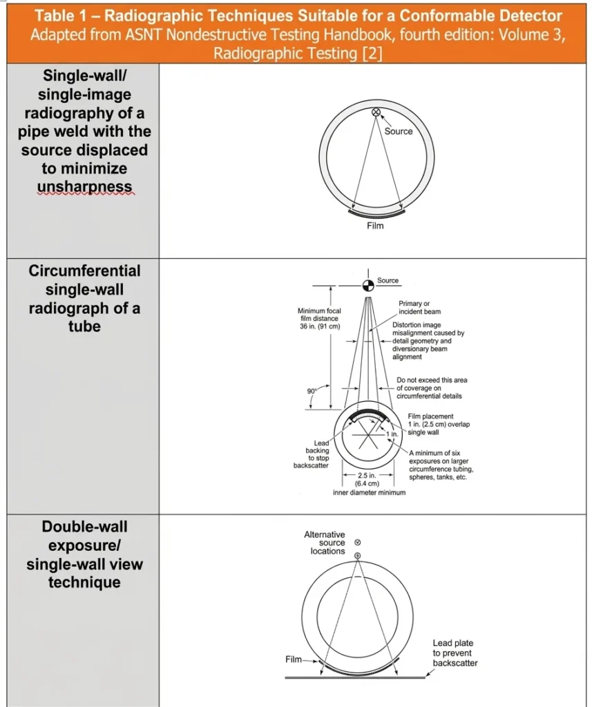
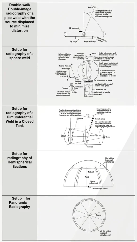
Regardless your level of experience on radiographic techniques , Table 1 aims to integrate into a single information element a collection of radiographic techniques that benefit from the availability of a conformable DR detector:
“Dose is King”
This expression is a mantra that seasoned radiographers often repeat to new apprentices. Dose describes the quantity of radiation produced for a specific exposure, and it is a concept that will be at the core of the hands-on, practical information on the “How’s” of the use of conformable detectors that we would like to share with you along this White Paper. An associated notion to dose that may influence your choice of distances and source-subject alignment in your radiographic technique will be the idea of dose rate which is the quantity of radiation produced as a function of time
To advance our understanding of the practical use of R-Factors on a conformable detector, we need to refresh a few concepts from our fundamental training as radiographers:
- A Roentgen (R) is a unit of exposure of X-ray or gamma radiation in air, whereby 1 R is the quantity of radiation that would ionize 1 cm3 of air to produce 1 electrostatic unit (ESU) of charge at standard pressure and temperature, and 1 ESU is equal to 3.3356 X 10- 10 Coulombs (C).
- A Rad is a unit of absorbed energy deposited in a mass of material,
- A Roentgen Equivalent Man (Rem) is a unit of dose absorbed by the human body.
- For X-ray or gamma radiation, a Roentgen is approximately equivalent to a Rad and a Rem.
- In simple terms, an R-factor is the total number of Roentgens needed to produce a specific film density or grey value in the radiograph and is an essential information element to help the radiographer decide the dose and dose rate to be used for an specific exposure.
How R-Factors are obtained
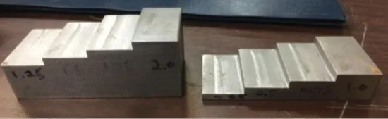
In this experimental setup to obtain the necessary information to establish the R-Factors, iridium, selenium, and cobalt radioisotope sources were utilized for the generation of the data. Steel step wedges (Figure 2) with thickness steps of 0.25″, 0.50″, 0.75″, 1.0″, 1.25″, 1.5″, 1.75″, and 2.0″ were utilized for the exposures.
The radiographic configuration setup is shown in Figure 3. The Source to Detector Distance (SDD) for film was 12″, and the SDD for the Digital Detector Arrays (DDAs) was 24″. The step wedges were masked with 1″ steel plates to control lateral scatter radiation.
![Figure 3: Radiographic shot configuration, from White [1]](https://cdn.inspenet.com/1-IMG-2-ESP-Como-construir-su-propio-caso-de-uso-para-un-detector-DR-conformable_resultado_resultado-1-1024x576.webp)
At least 100 mil of lead was placed between the detector and the wood table to control back scatter. Film exposures were done inside vinyl cassettes with 10-mil front-side lead screen, and 10-mil backside lead screen. The protective overcoat on both screens was peeled off for additional intensification. Iridium sources were approximately 50 Curies, with a diagonal focal spot of 0.15″. The selenium source was approximately 30 Curies, with a diagonal focal spot of 0.14″. The cobalt source was approximately 100 Curies, with a focal spot diameter of 0.15″.
DDA exposures were done with varying integration times and nine averaged frames. Iridium dose rate to the panel was 65.5 R/hour, selenium was 27.4 R/hour, and cobalt was 356 R/hour.
A 16-bit linear greyscale was utilized, and the file types were DICONDE compressed. Commercially available phone programs were utilized for the exposure calculations. The optical density or grey value was measured for the 1″ step for iridium, for the 0.25″ step for selenium, and for the 2″ step for cobalt. R factors to produce target optical density or grey values were calculated from the equations generated as a result of the exposure series data.
Our updated R Factor Tables that integrate results for a conformable DR detector
Table 2 compiles the R Factor results obtained by the set of experiments described above for five types of Caretream’s films using gamma radiation sources.
Gamma Radiation Source Type
| Iridium | Selenium | Cobalt | ||||||||||
| Density Desired | Density Desired | Density Desired | ||||||||||
| Film Type | 2.0 | 2.5 | 3.0 | 3.5 | 2.0 | 2.5 | 3.0 | 3.5 | 2.0 | 2.5 | 3.0 | 3.5 |
| M100 | 3.2 | 4.3 | 5.5 | 6.6 | 3.6 | 4.6 | 5.5 | 6.5 | 7.3 | 9.3 | 11.4 | 13.4 |
| MX125 | 2.3 | 3.1 | 3.9 | 4.7 | 2.2 | 2.9 | 3.6 | 4.4 | 3.9 | 5.3 | 6.7 | 7.9 |
| T200 | 1.1 | 1.5 | 2.0 | 2.4 | 1.4 | 1.8 | 2.2 | 2.6 | 2.3 | 3.1 | 3.9 | 4.7 |
| AA400 | 0.8 | 1.1 | 1.5 | 1.9 | 0.8 | 1.2 | 1.6 | 2.0 | 1.2 | 1.8 | 2.4 | 2.9 |
| HS800 | 0.2 | 0.5 | 0.7 | 0.9 | 0.3 | 0.6 | 0.8 | 1.0 | 0.1 | 0.6 | 1.0 | 1.4 |
![Table 2: Film R Factors for Gamma Radiation Sources, adapted from White [1]](https://cdn.inspenet.com/1-IMG-31-ESP-Como-elaborar-tu-propio-caso-de-uso-para-un-detector-de-DR-adaptable-1024x322.webp)
Table 3 compiles the R Factor results obtained by the set of experiments described above for four types of Carestream’s DDAs, including our HPX-DR 2530 PH conformable detector using gamma radiation sources. Values in this DR R Factor table are for a single acquired frame.
| Digital R Factor per frame for HPX-DR 3543 PE 16-Bit Linear | |||||||||||
| Pixel Intensity Desired | |||||||||||
| Source Type | 3000 | 6000 | 9000 | 12000 | 15000 | 18000 | 21000 | 24000 | 27000 | 30000 | 33000 |
| Iridium | 0.0112 | 0.0237 | 0.0366 | 0.0499 | 0.0635 | 0.0775 | 0.0918 | 0.0918 | 0.1216 | 0.1370 | 0.1528 |
| Selenium | 0.0011 | 0.0072 | 0.0113 | 0.0195 | 0.0258 | 0.0321 | 0.0384 | 0.0448 | 0.0513 | 0.0578 | 0.0644 |
| Cobalt | 0.0224 | 0.0529 | 0.0838 | 0.1151 | 0.1467 | 0.1787 | 0.2110 | 0.2437 | 0.2768 | 0.3102 | 0.3440 |
| Digital R Factor per frame for HPX-DR 2530 PC 16-Bit Linear | |||||||||||
| Pixel Intensity Desired | |||||||||||
| Source Type | 3000 | 6000 | 9000 | 12000 | 15000 | 18000 | 21000 | 24000 | 27000 | 30000 | 33000 |
| Iridium | 0.0084 | 0.0205 | 0.0328 | 0.0452 | 0.0577 | 0.0702 | 0.0829 | 0.0958 | 0.1087 | 0.1217 | 0.1348 |
| Selenium | 0.0021 | 0.0082 | 0.0144 | 0.0207 | 0.0270 | 0.0334 | 0.0399 | 0.0464 | 0.0530 | 0.0597 | 0.0665 |
| Cobalt | 0.0161 | 0.0434 | 0.0708 | 0.0984 | 0.1263 | 0.1542 | 0.1824 | 0.2108 | 0.2393 | 0.2680 | 0.2969 |
| Digital R Factor per frame for HPX-DR 2530 PH 16-Bit Linear * | |||||||||||
| Pixel Intensity Desired | |||||||||||
| Source Type | 3000 | 6000 | 9000 | 12000 | 15000 | 18000 | 21000 | 24000 | 27000 | 30000 | 33000 |
| Iridium | 0.0183 | 0.0423 | 0.0663 | 0.0904 | 0.1144 | 0.1385 | 0.1625 | 0.1866 | 0.2107 | 0.2348 | 0.2588 |
| Selenium | 0.0070 | 0.0190 | 0.0311 | 0.0431 | 0.0552 | 0.0673 | 0.0794 | 0.0915 | 0.1037 | 0.1158 | 0.1280 |
| Cobalt | 0.0586 | 0.1187 | 0.1788 | 0.2390 | 0.2993 | 0.3596 | 0.4199 | 0.4803 | 0.5408 | 0.6013 | 0.6619 |
| Digital R Factor per frame for HPX-ARC 1025 16-Bit Linear | |||||||||||
| Pixel Intensity Desired | |||||||||||
| Source Type | 3000 | 6000 | 9000 | 12000 | 15000 | 18000 | 21000 | 24000 | 27000 | 30000 | 33000 |
| Iridium | 0.0221 | 0.0431 | 0.0641 | 0.0851 | 0.1061 | 0.1271 | 0.1481 | 0.1457 | 0.1637 | 0.1817 | 0.1997 |
| Selenium | 0.0078 | 0.0198 | 0.0318 | 0.0438 | 0.0558 | 0.0678 | 0.0798 | 0.0953 | 0.1073 | 0.1193 | 0.1313 |
| Cobalt | 0.0590 | 0.1190 | 0.1790 | 0.2390 | 0.2990 | 0.3590 | 0.4190 | 0.4754 | 0.5354 | 0.5954 | 0.6554 |
| Digital R Factor per frame for HPX-ARC 1043 16-Bit Linear | |||||||||||
| Pixel Intensity Desired | |||||||||||
| Source Type | 3000 | 6000 | 9000 | 12000 | 15000 | 18000 | 21000 | 24000 | 27000 | 30000 | 33000 |
| Iridium | 0.0226 | 0.0466 | 0.0706 | 0.0946 | 0.1186 | 0.1426 | 0.1666 | 0.1906 | 0.2146 | 0.2386 | 0.2626 |
| Selenium | 0.1140 | 0.0234 | 0.0354 | 0.0474 | 0.0594 | 0.0714 | 0.0834 | 0.0954 | 0.1074 | 0.1194 | 0.1314 |
| Cobalt | 0.0553 | 0.1153 | 0.1754 | 0.2353 | 0.2953 | 0.3553 | 0.4153 | 0.4753 | 0.5353 | 0.5953 | 0.6553 |
*Note: The 2530 PH R factors can also be utilized for the HPX-DR 4336 GH (amplification gain setting of 4)
Table 3: Digital R Factor for Carestream’s DDAs
Brian White, Research Scientist and Level III Radiographer at Carestream NDT, explains the practical implications of the resulting updated R-Factors Tables for radiographer’s daily work in the following terms [3]: “Radiographers can utilize the tables to determine the R factor required for a target density or grey value. They can utilize a commercially available phone-based calculator to determine the exposure time required to obtain the target density or grey value. To calculate the time required, enter the source type, the activity of source in Curies, the steel thickness, the R factor, and the SDD. These exposure factors are meant to be a starting guideline only, as many other factors related to the part geometry and technique conditions will affect the final density or grey value. These exposure factor tables were verified for all systems presented in this paper. Overall, there was good agreement on exposure factor to target optical density or grey value.”
In the next section, we will follow Brian’s advice to obtain exposure times for several inspection conditions.
Exposure factors in practical use
Here is a practical example using a commercially available smartphone app devoted to exposure calculations. This app requires the following input parameters:
- The activity measurement units should be selected between Curies or Tera-Becquerels (TBq)
- The distance measurement units should be selected between inches or millimeters (mm)
- Selection of Gamma source type should be made—here the app allows to choose between Iridium
(Ir-192), Cobalt (Co-60) or Selenium (Se-75) - Input the following parameters:
- Activity in the selected measurement unit
- Steel thickness
- The exposure “R” factor:
- Typical R factors for film range from 1 up to 7, depending on film type and source type, CR is
similar to film for R factors. Please note how the R factors for DDA’s are significantly less as DDA’s
require significantly less exposure relative to film and CR, also note that these exposure factors are
meant to provide guidance for a starting point to set integration time.
I. First you need to decide which DDA you will be using for performing the radiographic test.
II. Once the DDA type is defined, you should establish the intended pixel intensity in the base metal
portion of the image.
III. Use Table 3 to select the proper “R” factor based in the selected DDA and which type of gamma
ray sources will be used.
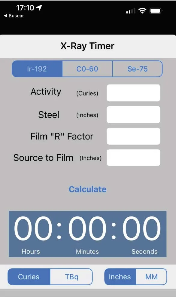
Press the word “Calculate” and the exposition time (or integration
time) will appear in the Hours:Minutes:Seconds field in the app.
Let’s roll up our sleeves and put these notions into practice by
solving an example provided by White in his presentation.
The test parameters are as follows:
- DDA type in use: HPX-ARC 1025
- Gamma radiation source: Iridium
- Source activity: 50 Curies
- Steel thickness: 0.5”
- Base metal target pixel intensity = 6000
- Source to DDA distance (SDD) = 24”
| Digital R Factor per frame for HPX-ARC 1025 16-Bit Linear | |||||||||||
| Pixel Intensity Desired | |||||||||||
| Source Type | 3000 | 6000 | 9000 | 12000 | 15000 | 18000 | 21000 | 24000 | 27000 | 30000 | 33000 |
| Iridium | 0.0221 | 0.0431 | 0.0641 | 0.0851 | 0.1061 | 0.1271 | 0.1481 | 0.1457 | 0.1637 | 0.1817 | 0.1997 |
| Selenium | 0.0078 | 0.0198 | 0.0318 | 0.0438 | 0.0558 | 0.0678 | 0.0798 | 0.0953 | 0.1073 | 0.1193 | 0.1313 |
| Cobalt | 0.0590 | 0.1190 | 0.1790 | 0.2390 | 0.2990 | 0.3590 | 0.4190 | 0.4754 | 0.5354 | 0.5954 | 0.6554 |
Based on a 6000 desired pixel intensity and the use of an Iridium source, the exposure or “R” factor is
0.0431 (see image above).
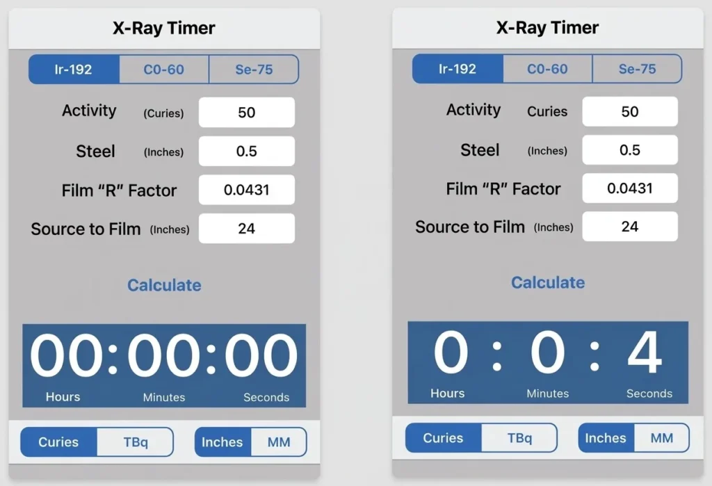
If you want to practice this calculation process using the HPX-ARC 1025 with a different set of
parameters, Table 4 provides four supplementary examples that you can use.
| Table 4 | ||||
| Parameter: | Example 1 | Example 2 | Example 3 | Example 4 |
| DDA Type | Digital R Factor for HPX-ARC 1025 | |||
| Gamma radiation source | Cobalt | Selenium | Iridium | Iridium |
| Source Activity | 35 | 50 | 75 | 75 |
| Steel Thickness: | 3.5” | 0.5” | 1” | 2” |
| Base metal target pixel intensity | 6000 | 6000 | 6000 | 6000 |
| SDD | 40 | 20 | 20 | 30 |
| Results | ||||
| “R” Factor | 0.1190 | 0.0198 | 0.0431 | 0.0431 |
| Integration Time | 1 minute 59 seconds | 4 seconds | 4 seconds | 28 seconds |
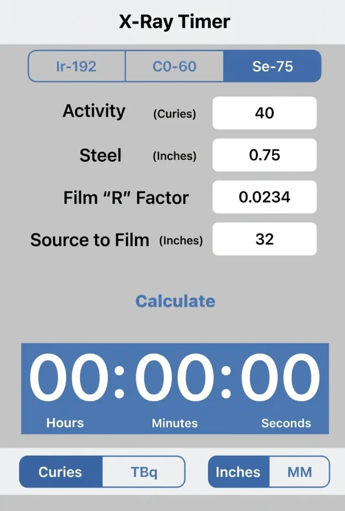
Now, let’s roll up our sleeves again and explore the exposure factors
for the HPX-ARC-1043. The test parameters are as follows:
- DDA type in use: HPX-ARC 1043
- Gamma radiation source: Selenium
- Source activity: 40 Curies
- Steel thickness: 0.75”
- Base metal target pixel intensity = 6000
- Source to DDA distance (SDD) = 32”
| Digital R Factor per frame for HPX-ARC 1043 16-Bit Linear | |||||||||||
| Pixel Intensity Desired | |||||||||||
| Source Type | 3000 | 6000 | 9000 | 12000 | 15000 | 18000 | 21000 | 24000 | 27000 | 30000 | 33000 |
| Iridium | 0.0226 | 0.0466 | 0.0706 | 0.0946 | 0.1186 | 0.1426 | 0.1666 | 0.1906 | 0.2146 | 0.2386 | 0.2626 |
| Selenium | 0.1140 | 0.0234 | 0.0354 | 0.0474 | 0.0594 | 0.0714 | 0.0834 | 0.0954 | 0.1074 | 0.1194 | 0.1314 |
| Cobalt | 0.0553 | 0.1153 | 0.1754 | 0.2353 | 0.2953 | 0.3553 | 0.4153 | 0.4753 | 0.5353 | 0.5953 | 0.6553 |
Based on a 6000 desired pixel intensity and the use of an Iridium source, the exposure or “R” factor is
0.0234 (see image above).
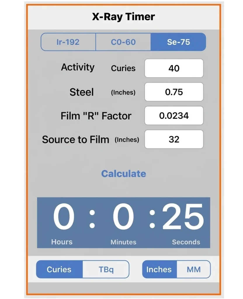
For further exploration of the calculation process employing the exposure factors for HPXARC
1043, Table 5 presents four additional illustrative examples.
| Table 5 | ||||
| Parameter: | Example 5 | Example 6 | Example 7 | Example 8 |
| DDA Type | Digital R Factor for HPX-ARC 1025 | |||
| Gamma radiation source | Cobalt | Selenium | Iridium | Iridium |
| Source Activity | 40 | 45 | 50 | 45 |
| Steel Thickness: | 3.0” | 0.75” | 1.25” | 1.75” |
| Base metal target pixel intensity | 6000 | 6000 | 6000 | 6000 |
| SDD | 40 | 30 | 25 | 30 |
| Results | ||||
| “R” Factor | 0.1153 | 0.0234 | 0.0466 | 0.0466 |
| Integration Time | 1 minute 7 seconds | 20 seconds | 3 seconds | 5 seconds |
An actionable approach for radiographic imaging
professionals and business decision-makers – Building your
own use case for a conformable DR detector (Part II of III)
After completing columns A, B and C of your analysis table, following the guidelines provided in the
first white paper of this series, you should proceed to compare alternative radiographic techniques:
E. As an initial step in this stage, and for each of the elements in your list of the components and
assemblies within the scope of your work that require radiographic imaging processes, annotate the
number of images that you should obtain per exposure.
F. Next, for each component or assembly type make the calculation of the exposure time using your
current radiographic technique).
G. Then, for each component or assembly type make a new calculation of the exposure time using the
R Factor for the HPX-ARC 1025 obtained from Table 3 on this White Paper.
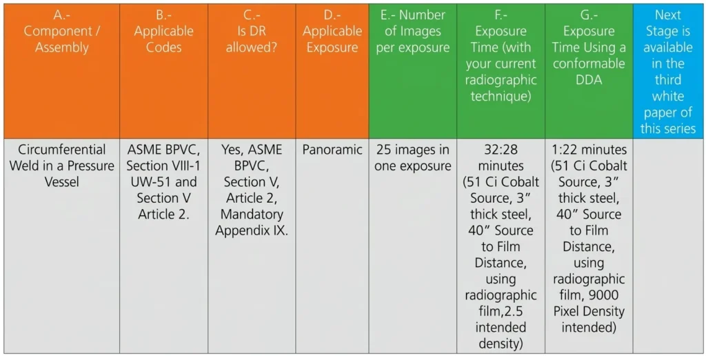
At this stage, you should have consolidated into a single document not only a comprehensive list of the
most common components or assembles where you need to perform radiographic imaging processes,
which of those radiographic imaging applications have the option to be performed with DR and which
are suitable to use a conformable DR detector, but comparative data of exposure time savings that will
be invaluable for our productivity analysis in the next stage.
To move forward in the construction of your business case, we advise you to review other White Papers in this series:
Building your own use case for a conformable DR detector
Part I – “The Why’s” Expanding, Enriching and Reinforcing Your Imaging Capabilities
Part II – “The How’s” Proposing an actionable approach to a new set of imaging capabilities (This White Paper)
Part III – “The What’s” An Instructive Comparison of Conformable DDAs to Film and CR Imaging Plates
Here are some supplementary information resources from Carestream NDT’s products and services portfolio:
- For readers interested in exploring how digital radiography (DR) can be integrated into your processes: https://www.carestream.com/en/us/nondestructive-testing-ndt-solutions
- For readers interested in exploring supplementary white papers on practical application and innovation on imaging processes: https://www.carestream.com/en/us/nondestructive-testing-ndt-solutions/ndt-white-papers
Here are some supplementary information resources from Carestream NDT’s products and services portfolio:
Products
• HPX ARC 1025 PH
• HPX ARC 1043 PH
• INDUSTREX Fieldview, Tablet
• INDUSTREX Digital Viewing Software
• Advanced Industrial Radiographic Training Academy
• ayData NDT Archive Solution
• Virtual NDT Showcase
• Resource Center
• NDT White Papers
Services – Training and Supplementary Resources:
Resources from ASNT
Services – Training and Supplementary Resources:
- Digital Detector Array Radiography – 40 Hour Online Course
- Digital Imaging – 40 Hour Classroom Training
Resources from ASNT
References
- White, Brian S. “Exposure Factors for Film and Digital Detector Array Radiography,” 20th World Conference on Nondestructive Testing, Incheon, South Korea, 2024.
- Bossi, R., Nondestructive Testing Handbook, fourth edition: Volume 3, Radiographic Testing, Columbus, OH, American Society of Nondestructive Testing, 2019.
- Sinek, Simon. Start with why: How great leaders inspire everyone to take action. Penguin, 2009.