Table of Contents
In floating roof tanks, loss of contact between the rim seal and the shell can open leakage paths that are difficult to detect. Evaporative losses in tanks generate product losses, volatile organic compound (VOC) emissions, and conditions that increase fire risk in the rim space.
Technical evaluation must consider tank geometry, radial force, material response, traceability, inspection, and verification of system efficacy. Under this approach, the seal acts as an active barrier for operational safety, emission control, and inventory conservation.
Evaporative losses in floating roof tanks
Evaporative losses in storage tanks do not come from a single source. In floating roof tanks, the rim seal accounts for a fraction of emissions, but deck fittings, seams on certain bolted internal decks, and product remaining adhered to the shell as the level drops also play a role.
The EPA AP-42 Chapter 7.1 methodology separates these sources to estimate their contribution. This differentiation helps determine whether the loss comes from the rim space, deck penetrations, or an operational condition requiring a different corrective measure.
Wind action on the rim space
In external floating roofs, wind creates pressure variations around the deck and promotes vapor turnover at any discontinuity. A short but wide and exposed gap can release more vapor than several small gaps distributed around the circumference.
Inspection must log the location, length, width, and evolution of each gap at different fill levels. Rim loss also depends on product volatility, tank diameter, and site meteorological conditions.
Seals in internal floating roofs
In an internal floating roof tank, the floating deck operates beneath a fixed roof that protects it from rain, solar radiation, and direct wind action. This configuration reduces environmental exposure of the seal, but does not eliminate emissions: vapor can escape through the rim space, deck fittings, and seams of bolted internal decks.
Unlike external floating roofs, no dominant wind-induced loss mechanism has been identified in internal floating roofs. Control depends mainly on circumferential fit, barrier continuity, material permeability, deck joints, and fitting closures.
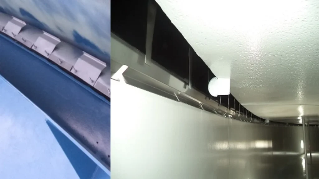
The system can use only a primary seal or incorporate a secondary seal on a vertical plate extended from the rim. This second barrier provides additional control over residual vapor, provided it maintains continuous contact and allows vertical movement of the deck.
Tank seal quality under real conditions
Tank seal quality expresses the system’s ability to maintain containment during service. A membrane may appear intact yet have lost sealing capacity due to relaxation, abrasion, or vapor permeation through the material. A metallic assembly can also create gaps if its travel does not compensate for out-of-roundness, protruding welds, or roof off-centering.
Selection must consider the stored product, temperature, rim space variation range, and environmental exposure. Material, geometry, and contact force must work together to maintain rim closure without restricting vertical movement of the roof.
Radial force, friction, and movement
Radial force is one of the most critical operating factors. Insufficient loading allows wind or rim space variation to separate the barrier from the shell. The seal loses closure capacity and emissions increase, even if the membrane retains an acceptable appearance.
Excessive loading increases friction, accelerates abrasion, can fold or tear the membrane, and raises the risk of binding against shell irregularities. Engineering must establish a stable contact range that allows vertical movement without subjecting the system to unnecessary stress.
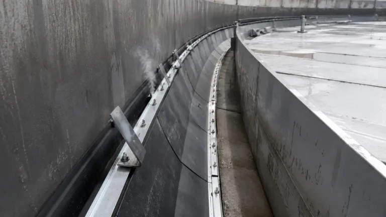
In mechanical shoe seals, this contact force can be generated through various configurations of springs, linkage mechanisms, or compression elements. The selected architecture must absorb rim space variations and keep the plates close to the shell throughout roof travel, while the vapor barrier maintains seal continuity.
This principle can be observed in two configurations developed by COTESO. In the COT1, metallic shoe plates press against the shell via a scissor-type linkage mechanism and leaf springs, while a vapor barrier completes the seal. The design adapts to the specific geometry of the tank and responds to significant rim space variations.
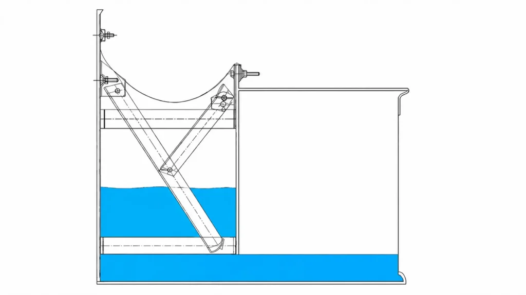
The COT30 uses a different mechanical principle: compression plates generate sealing pressure against the shell and are backed by stainless steel leaf springs. A PTFE vapor barrier positioned between both components completes the seal. In both configurations, the objective is to maintain contact pressure stable enough to limit vapor passage while simultaneously permitting vertical movement of the roof without generating friction or stresses that compromise the system.
Traceability and MTR certificates
Seal acceptance requires more than a visual inspection. The quality plan must include component identification, batch traceability, dimensional inspection, joint inspection, and records linking the approved design to the executed installation.
Material Test Reports (MTRs) verify the chemical composition, mechanical properties, and origin of metallic materials. They must be supplemented by manufacturing records, joint inspection, and assembly control. For membranes and polymeric components, specific manufacturer datasheets and certificates are required.
Materials based on service conditions
Flexible barriers must be evaluated for their resistance to vapor passage or permeation, tearing, abrasion, and flex fatigue. Their response to hydrocarbons, ultraviolet radiation, ozone, and temperature changes is also important.
For metallic components, stiffness, elastic recovery, corrosion, and the behavior of fasteners, springs, or linkages are key. Simply specifying PTFE, NBR, EPDM, FKM, galvanized steel, or stainless steel is insufficient without relating them to the product, geometry, and expected service life.
This relationship can be observed in the COT30 design, where COTESO incorporates a PTFE vapor barrier between the seal plates and spring system. Selection is not based solely on the presence of the polymer: it must consider compatibility with the stored product and prolonged exposure to ozone, UV radiation, rainwater, and temperature variations. For metallic parts, the manufacturer considers different grades of stainless steel and galvanized steel based on service conditions.
Safety in storage tanks
Storage tank safety requires controlling vapor releases and ignition sources. When a gap discharges VOC vapors toward the roof perimeter, a flammable mixture can form if concentration reaches the range between the lower and upper flammability limits.
Seal deterioration does not automatically cause a fire, but it increases the amount of fuel available in the vapor phase. The ultimate risk depends on volatility, ventilation, temperature, electrical continuity, and control of hot work capable of producing heat, arcs, or sparks.
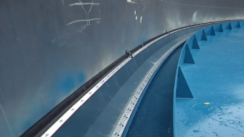
In external floating roofs, a properly fitted secondary seal adds a second barrier over the rim space and limits vapor release not contained by the primary system. An example is COTESO’s COT20L, a compression plate secondary seal where the plates maintain an elastomeric tip in contact with the shell, while a vapor barrier behind the assembly completes the seal. Operating independently from the primary seal, its performance depends on continuous contact with the shell, rim space geometry, and material compatibility with service conditions.
Fire protection and safe intervention
The sealing system must be compatible with foam dams, discharge chambers, and other protection elements. NFPA 11 covers low-, medium-, and high-expansion foam systems, while comprehensive management also requires grounding, bonding, detection, and emergency response.
During seal maintenance or retrofit, a distinction must be made between non-sparking tools and intrinsically safe equipment. Non-sparking tools reduce the likelihood of impact or friction sparks; intrinsically safe equipment consists of electrical devices designed to limit available energy and prevent ignition of a hazardous atmosphere. Neither category replaces classified area evaluation or atmospheric monitoring.
VOC emissions in tanks using TANKS 5.3
Quantification transforms hard-to-value leaks into quantifiable evaporative losses, useful for engineering, inventory control, and environmental compliance. API MPMS 19.2 addresses evaporative loss from floating roof tanks, while API MPMS 19.3 Part B establishes an air concentration test method to determine rim seal loss factors.
The official EPA tool TANKS 5.3 uses chemical, meteorological, tank, deck fitting, and rim seal data to estimate VOC and hazardous air pollutant (HAP) emissions from fixed and floating roof tanks. Its results depend on the quality of input data and must be verified against the physical condition of components.
Equations for loss calculation by source
For routine operation, the balance can be expressed as:
Lt=Ls+Lw
Where Lt represents total routine losses, Ls standing losses, and Lw withdrawal losses due to product adherence to the shell during level decline.
In turn:
Ls=Lr+Lf+Ld
Where Lr corresponds to rim seal losses, Lf to deck fitting losses, and Ld to deck seam losses on bolted internal floating roofs. This balance prevents attributing the entire loss to the seal before inspecting other emission routes.
Regulatory gap measurement
Gaps in floating roof seals must be evaluated according to applicable regulations. As a U.S. reference, 40 CFR 63.1063 describes a probe procedure for measuring length, width, and accumulated area on external floating roofs subject to that rule.
Reference table: regulatory gap limits per 40 CFR 63.1063
| Seal type | Maximum accumulated area | Maximum allowable width |
|---|---|---|
| Primary seal | ≤212 cm2 per meter of diameter (10.0 in2/ft) | 3.81 cm (1.50 in) |
| Secondary seal | ≤21.2 cm2 per meter of diameter (1.0 in2/ft) | 1.27 cm (0.50 in) |
Application note: These limits originate from 40 CFR 63.1063(d)(3)(ii)–(iii) and apply to tanks subject to that subpart or standards incorporating it by reference. Outside the United States, local environmental regulations, permits, and authority criteria must be reviewed.
Costs of evaporative losses
Every kilogram of hydrocarbon emitted represents purchased, processed, transported, and stored product that is no longer available for sale or transfer. Direct loss can be estimated using:
Annual loss=evaporated mass×unit recoverable value
The recoverable value can be based on replacement cost, contribution margin, internal transfer value, or net price. In complex mixtures, vapor may contain a higher proportion of light, volatile components; using the average liquid price may distort the economic impact.
Indirect costs and product quality
Financial impact also includes environmental metering, reporting, unscheduled inspections, corrective maintenance, spare parts, and downtime. To avoid double counting, each item should be associated with an independent cash flow within the terminal’s financial model.
Preferential evaporation of volatile components can alter vapor pressure, density, or commercial specification of the remaining product. In certain operations, this quality degradation can exceed the cost of volumetric loss.
Tank seal retrofit and return on investment
A tank seal retrofit should begin with a documented baseline including installed configuration, gap map, barrier condition, stored product, temperature, wind, operational cycles, estimated emissions, and historical costs. This evaluation prevents replacing the seal when the main emission route lies in deck fittings or seams.
Once confirmed that the rim space is a significant loss source, retrofit is no longer just component replacement. Actual shell geometry, required radial travel, rim gap variations, chemical compatibility, contact pressure, and conditions encountered across all operating roof levels must be evaluated.
For modernization projects, COTESO offers floating roof seal systems, including liquid-mounted primary shoe plate systems developed for external floating roof tanks. The COT1 uses metallic shoe plates, linkage mechanisms, leaf springs, and a vapor barrier; the COT30 uses compression plates, stainless steel springs, and a PTFE barrier. In both designs, the basic configuration adapts to the geometric and service conditions of each tank.
Design differences are relevant during retrofit engineering because the mechanism used to generate pressure against the shell affects seal capacity to absorb rim space variations, preserve the vapor barrier, and accompany vertical roof travel. Selection must stem from measured asset conditions and not solely existing seal configuration.
Under this approach, retrofit can integrate dimensional survey, material selection, engineering, manufacturing, and system installation. The technical goal is to restore stable circumferential contact and reduce the identified emission route, avoiding attributing to the new seal losses that actually originate from fittings, penetrations, or other deck discontinuities.
Economic evaluation of the project
Total investment must include dimensional survey, engineering, materials, manufacturing, transportation, installation, supervision, commissioning, and downtime. Net annual savings can be expressed as:
Net annual savings=conserved product+avoided costs−new operating expenses
The simple payback period is calculated using:
Simple payback=net annual savingstotal investment
Analysis requires evaluating price changes, volatility, weather conditions, service life, and maintenance frequency.
Acceptance and operational monitoring
After assembly, circumferential contact, radial tension, freedom of movement, joints, fasteners, absence of interferences, and vapor barrier condition must be verified. Inspection should compare installed conditions against design and acceptance criteria.
Monitoring can integrate gap maps, emission recalculations, inventory trends, and visual inspections. Optical gas imaging (OGI) cameras and portable VOC detectors serve as support when procedures and environmental conditions allow proper interpretation of results.
Conclusion
Evaporative losses in floating roof tanks allow evaluating industrial safety, seal functional quality, and inventory efficiency. The decisive parameter is system capacity to maintain contact, limit vapor passage, and adapt to shell geometry throughout each operational cycle. The complementary use of AP-42, API MPMS, TANKS 5.3, NFPA 11, and gap regulations provides a verifiable basis for diagnosing emissions and justifying a retrofit. Under this approach, the seal becomes a critical component for safety, loss control, and operational performance.
References
- U.S. EPA. AP-42, Chapter 7, Section 1: Organic Liquid Storage Tanks.
- API. MPMS Chapter 19.2, Evaporative Loss from Floating-Roof Tanks.
- API. MPMS Chapter 19.3, Part B — Air Concentration Test Method — Rim Seal Loss Factors for Floating Roof Tanks.
- eCFR. 40 CFR §63.1063, Floating Roof Requirements.
- COTESO. COT1 Liquid Mounted Primary Shoe Plate Seal. Product Datasheet.
- COTESO. COT30 Liquid Mounted Primary Shoe Plate Seal. Product Datasheet.
- COTESO. COT20 Secondary Compression Plate Seal. Product Datasheet.
- COTESO Group. Tank Seals for Floating Roofs.
Frequently asked questions (FAQs)
What causes evaporative losses in floating roof tanks?
Seal gaps, product volatility, wind action, and leaks through deck fittings or seams.
How does a deteriorated seal affect tank safety and operation?
It increases VOC emissions, product losses, and the presence of flammable vapors in the rim space.
When is it recommended to perform tank seal retrofits?
When savings from conserved product and avoided costs justify the investment required to modernize the system.