Table of Contents
- The project site as a design starting point
- Why an aluminum dome and not a steel roof?
- Sliding supports (shoes): Decoupling the dome from the shell
- Perimeter sealing and centralized ventilation
- Top platform and access to instrumentation
- The water tank: Why a different standard?
- Preliminary engineering, fabrication, and site supervision
- Conclusions
- References
- Frequently asked questions
When evaluating a roof requirement for storage tanks, the first question is not what product to offer, but what conditions the structure will have to withstand throughout its service life. The answer is rarely in a catalog: it is at the site.
In the facilities in the Los Lagos Region in which we participated, those conditions converged unusually. The site is located on the subduction margin between the Nazca and South American plates, in the same region where the largest magnitude earthquake ever measured was recorded. It is located on the shores of Chincui Bay, an area of frequent rainfall. High seismicity, a marine atmosphere, and a sustained rainfall regime act simultaneously on the same structure.
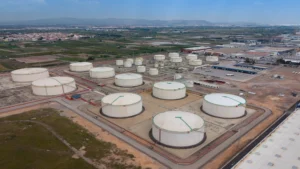
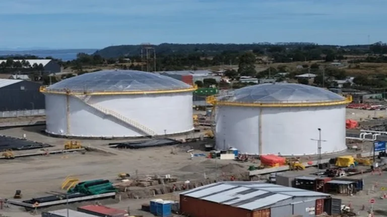
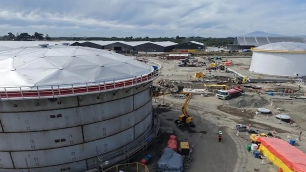
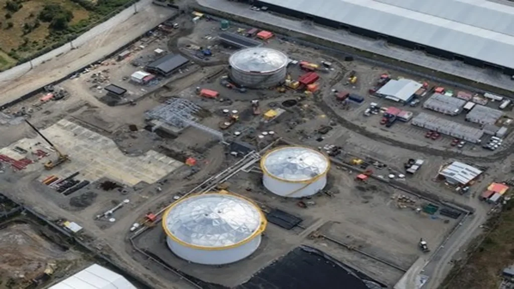
At COTESO Chile SpA, we supplied three aluminum geodesic domes for this project. Our scope was not limited to equipment: we performed the engineering review of the tanks before defining the design of each dome and provided specialized supervision during on-site assembly.
This article outlines the technical criteria that determined each of those decisions: why aluminum and not steel, why sliding supports instead of fixed supports, why perimeter sealing with centralized ventilation, and why two different regulatory frameworks in a single project. We do so because we understand that the value of a storage solution does not reside in the equipment delivered, but in the alignment between that equipment and the actual conditions of the site where it will perform for decades.
The project site as a design starting point
The facilities are located on private grounds of ESMAX Distribución and OXXEAN, in an area extending from the dock sector in Chincui Bay to the Chinquihue HJ-2 property, in the upper part of the bay, next to the public road connecting Cruce Paredes, Route 5 South, and Pargua.
Three characteristics of that site condition the structural design of a tank roof, and none of them can be treated as a later adjustment.
Seismicity. The Los Lagos Region is situated on the subduction margin between the Nazca and South American plates, the same area where the largest magnitude earthquake ever measured was recorded in 1960. Any structure mounted on a tank in this environment must be conceived considering significant relative displacements, not just static loads.
Marine atmosphere. Proximity to saltwater implies permanent exposure to airborne chlorides, the agent that most accelerates the atmospheric corrosion of carbon steel. On a metallic roof, this exposure determines the maintenance cycle for decades.
Precipitation regime. Southern Chile experiences frequent rainfall with a wind component. For a dome, this translates into two simultaneous requirements: preventing water ingress around the perimeter and maintaining adequate ventilation of the vapor space.
Scope of supply and dome specifications
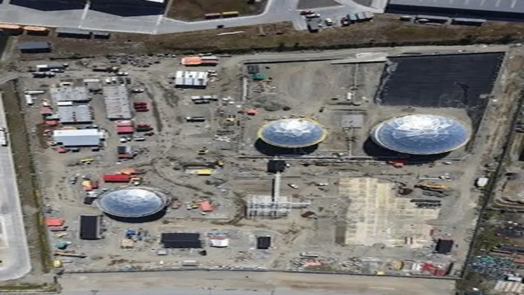
The executed scope comprised three aluminum geodesic domes, distributed as follows:
| Equipment | Diameter | Service and applicable standard |
| Geodesic dome | 24.4 m | New storage tank, designed in accordance with API 650 |
| Geodesic dome | 34.1 m | New storage tank, designed in accordance with API 650 |
| Geodesic dome | 24.4 m | Water storage tank, designed in accordance with AWWA standards |
Why an aluminum dome and not a steel roof?
The choice of aluminum as a roofing material is often presented as a generic advantage. In a site like this, however, it answers specific reasons that are worth distinguishing.
Performance against atmospheric corrosion
Aluminum spontaneously develops a passive oxide layer that isolates the metal from the aggressive medium and protects it from atmospheric corrosion without requiring coatings. In a marine environment, this property eliminates the surface preparation and repainting cycle that a carbon steel roof requires on a recurring basis, along with the scaffolding, work permits, and downtime associated with that intervention.
The difference does not lie in the initial cost, but in the asset’s life cycle cost. A steel roof in a saline atmosphere does not fail by design: it degrades through deferred maintenance, and the aluminum dome removes that variable from the equation.
Strength-to-weight ratio and load transmitted to the tank shell
An aluminum geodesic dome is lighter than a steel roof of equal dimensions. This weight reduction represents two key advantages in seismic zones: on one hand, it reduces the mass at the upper elevation of the tank, precisely where a high value produces the greatest overturning moment during an event; on the other hand, it decreases the dead load that the shell must transmit to the foundation.
Annex G of API 650 establishes that, in new tanks, the structure must be designed to support the dome, and that the roof manufacturer must supply the magnitude and direction of all forces it transmits to the tank. Due to this technical interaction, the engineering review of the tank cannot be carried out after the dome design: both definitions are strictly interdependent.
Self-supporting structure without internal columns
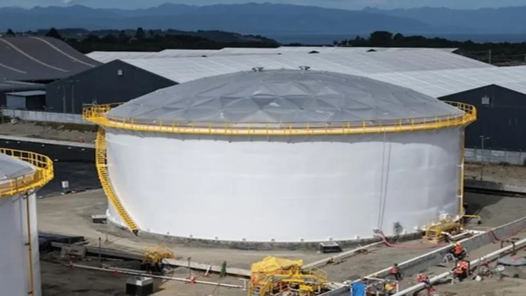
Pursuant to Annex G of API 650, a structurally supported aluminum dome is a fully triangulated space frame, with bars joined at nodes arranged on the surface of a sphere and aluminum closure panels securely attached to the frame. The structure rests solely on the top rim of the shell, at equidistant mounting points along the perimeter.
The absence of internal columns has operational implications that extend beyond structural aspects: it eliminates penetrations through the internal space, simplifies inspection of the tank interior, and avoids the interferences that a column introduces when the tank incorporates an internal floating roof.
Structural design in accordance with this annex must comply with the Aluminum Design Manual, including second-order non-linear analysis. This requirement is not a formality: in slender aluminum structures, non-linear behavior determines the real stability of the assembly, and a first-order analysis can prove non-conservative.
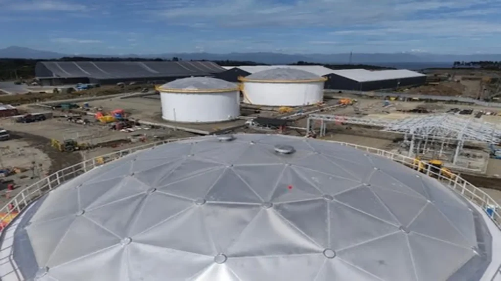
In the following image, the fully triangulated space frame can be seen with nodes arranged on a spherical surface, and the central vent at the apex.
Sliding supports (shoes): Decoupling the dome from the shell
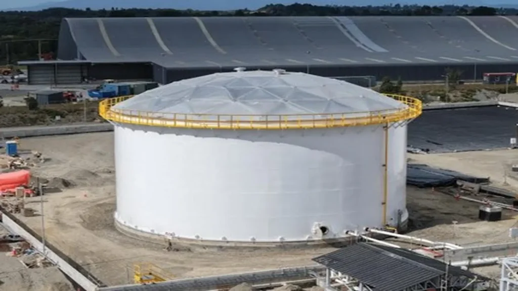
Among the technical features incorporated, the one we consider decisive for this site is the provision of supports with sliding shoes, designed to accommodate deformation and vibration by allowing the required structural movement without compromising overall performance.
The reason for this decision is explained on three levels.
Differential thermal expansion between aluminum and steel
Aluminum has a linear thermal expansion coefficient close to 23 × 10⁻⁶ K⁻¹, approximately double that of carbon steel, which is around 12 × 10⁻⁶. In a 34.1 meter diameter dome, this difference produces noticeable perimeter displacements due to daily ambient temperature variations.
If the supports were fixed, this incompatibility of deformations would translate into cyclic horizontal stresses concentrated at the connections, with the consequent risk of long-term fatigue. The sliding support allows both materials to deform according to their own behavior without transferring loads to each other.
Structural behavior of the shell and its connection to the dome
A tank wall is not a geometrically invariable surface. Product level variations modify the hydrostatic pressure on the lower shell course (ring), and with it, the effective diameter of the shell. Added to this are deviations in roundness and verticality resulting from construction and foundation settlement.
This movement of the shell occurs regardless of the type of support connecting the dome to its top rim; what changes depending on the support is whether or not that movement is transmitted to the roof structure. With a fixed support, the dome remains rigidly attached to the shell and is forced to follow that movement, inducing additional stresses in its structure.
The sliding support, in contrast, decouples both elements: it allows the top edge of the shell to displace freely in the radial plane, without dragging the dome along or transmitting the loads associated with that movement. Therefore, sliding support is recommended over fixed support because it decouples the inevitable movement of the shell.
Response to seismic events
During an earthquake, a storage tank experiences shell displacements and movement of the contained liquid. Annex G of API 650 establishes that when the tank is designed for seismic loads, the roof must be designed for the horizontal and vertical accelerations defined in Annex E of the same standard.
In this context, the sliding support serves an additional function to accommodating expansion: it allows relative movement between the shell and the dome during the event, rather than concentrating the entire demand on a reduced number of connection points. It is a design decision that separates the behavior of two elements that would otherwise be forced to respond as a single body.
Perimeter sealing and centralized ventilation
Each dome incorporates a solid sealing system fitted around the entire perimeter of the structure. This configuration prevents airflow through the perimeter and enables ventilation through central vents provided for that purpose.
The rationale is as follows. A fixed-roof tank requires vapor space ventilation, but the pathway through which that ventilation occurs is not irrelevant. When air enters diffusely through the joint between the dome and the shell, the flow rate is no longer controllable, and in a location with wind-driven rain like Chincui Bay, that same opening becomes an ingress route for wind-blown water.
By sealing the perimeter and concentrating ventilation in central devices sized for that purpose, airflow becomes predictable, and rainwater is excluded from the interior. When the tank incorporates an internal floating roof, this configuration gains additional relevance, as water ingress compromises both product quality and the operation of the floating roof itself.
Top platform and access to instrumentation
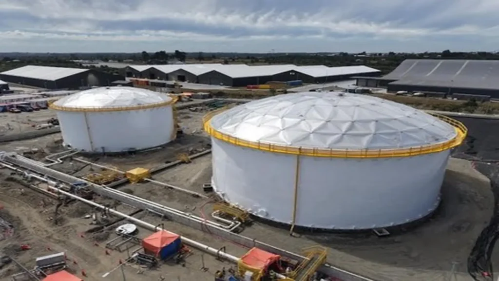
All three domes are equipped with a platform at their apex, providing personnel with safe access to the measurement and monitoring instruments installed on the tanks.
This decision addresses an operational reality that is often dealt with too late. Level, temperature, and pressure instrumentation require periodic verification, calibration, and maintenance throughout the tank’s service life. Without a platform designed from the outset, these activities end up being performed using provisional access methods, introducing working-at-height risks and often leading to the deferral of interventions that should be routine.
Incorporating access into the structure from the beginning converts a high-risk task into a schedurable one. It is a maintenance engineering consideration applied during the design phase, which is where it has the greatest effect and lowest cost.
The water tank: Why a different standard?
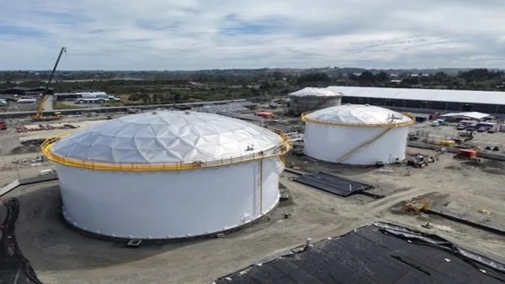
The third dome, 24.4 meters in diameter, was supplied for a water storage tank designed in accordance with AWWA standards. The coexistence of two regulatory frameworks in a single project is not an administrative anomaly: it responds to the fact that these are different services, with distinct design criteria.
API 650 governs welded steel tanks for oil storage and other products at atmospheric pressure or near it, and its Annex G covers structurally supported aluminum domes. In the water sector, standard AWWA D100 covers welded carbon steel tanks for water storage, explicitly stating that, with the exception of aluminum domes, it does not apply to tanks built with materials other than carbon steel.
This exception is elaborated in standard AWWA D108, which establishes the minimum requirements for the design, fabrication, and erection of structurally supported aluminum dome roofs for water storage facilities, originating from the corresponding section of AWWA D100. When this standard is specified, its requirements govern in the event of a conflict with other applicable standards.
In practice, this means that the water tank dome and those of the product tanks share the same structural principle but respond to separate regulatory frameworks, and their design verification must be conducted through equally separate paths.
Preliminary engineering, fabrication, and site supervision
Tank engineering review
Our scope did not begin with fabrication, but with the review of the tank engineering, a phase we consider decisive to developing an accurate design for each dome and ensuring its integration with the projected structures.
The reason is what we outlined earlier: Annex G of API 650 requires the tank to be designed to support the dome and the roof manufacturer to provide the forces transmitted by the structure. This requirement can only be met if both engineering designs are reviewed jointly rather than sequentially. Verifying shell geometry, top-rim detailing, and support conditions before defining the dome prevents field corrections, which are the most costly and impact the schedule the most.
Design, fabrication, transportation, and delivery
Subsequently, we undertook the design, fabrication, transportation, and delivery of the domes to the project site. This comprehensive participation allowed us to address the various stages of the supply process in a coordinated manner, taking into account technical and regulatory requirements alongside the specific conditions of each tank.
The prefabricated, bolted nature of the structure represents a primary logistical advantage in a remote location: the dome is transported knocked-down in manageable volumes and assembled on site without requiring welding processes or heavy-duty lifting equipment.
Specialized supervision during assembly
The structures were installed by the contractor PUMA, Puga & Mujica Asociados, with on-site supervision by a COTESO specialist.
This technical guidance made it possible to instruct the installation team on the specific characteristics of the structures and address situations arising during the assembly process in a timely manner. The coordinated effort between both companies enabled the installation to be completed efficiently and within the established project schedule.
We consider that this stage deserves a note. A geodesic dome is a sequentially assembled structure in which tolerances accumulate: a deviation introduced in the initial rings is amplified toward the perimeter. Specialized supervision does not replace the erection contractor; it ensures that the design criteria are accurately translated to the field, which is where it is ultimately determined whether the structure will perform as calculated.
Conclusions
A storage project in Chincui Bay is not solved by selecting catalog equipment. Subduction seismicity, a saline atmosphere, and sustained precipitation form a set of demands that require deliberate decisions regarding roof material, connection methods to the tank itself, perimeter management, and the provision of access required for maintenance over decades.
At COTESO, we approach these types of requirements from initial engineering review through to specialized field assistance, because the alignment between design and site conditions is not verified at delivery, but across the entire service life of the asset. Our involvement in this initiative strengthens our expertise in storage tank solutions and projects that demand high technical standards, multidisciplinary coordination, and compliance with international standards.
References
- American Petroleum Institute. (2020). API Standard 650: Welded tanks for oil storage (13.ª ed.), Anexo E y Anexo G. API.
- American Water Works Association. (2021). ANSI/AWWA D100: Welded carbon steel tanks for water storage. AWWA.
- American Water Works Association. (2019). ANSI/AWWA D108-19: Aluminum dome roofs for water storage facilities. AWWA. https://store.awwa.org/AWWA-D108-19-Aluminum-Dome-Roofs-for-Water-Storage-Facilities
- The Aluminum Association. (2020). Aluminum Design Manual. The Aluminum Association.
Frequently asked questions
What is an aluminum geodesic dome for storage tanks?
It is a fully triangulated space frame, with bars joined at nodes arranged on the surface of a sphere and aluminum panels attached to the frame. It rests solely on the top rim of the tank shell at equidistant perimeter points, without requiring internal columns. Annex G of API 650 governs its design for hydrocarbon tanks, while AWWA D108 does the same for water storage facilities.
Why is aluminum preferred over steel for tank roofs?
For three reasons acting simultaneously. Aluminum forms a natural oxide layer that protects it from atmospheric corrosion without coatings, eliminating the repainting cycle in marine environments. Its lighter weight reduces the mass located at the top of the tank, which is favorable under seismic demand. And it allows covering large spans without internal columns, offering operational advantages for inspection and for tanks with internal floating roofs.
What is the purpose of sliding supports on an aluminum dome?
They decouple the dome’s behavior from the tank shell. They accommodate differential expansion between aluminum and steel, whose coefficients differ by approximately a factor of two; absorb dimensional variations of the shell associated with product level and out-of-roundness deviations; and, during a seismic event, allow relative movement between both elements rather than concentrating demand at the connections.
Can a geodesic dome be installed on an existing tank?
Yes, and it is a common application on external floating roof tanks. Annex G of API 650 establishes a specific requirement in this case: the roof manufacturer must verify that the tank has sufficient strength to support the new roof and meet applicable requirements. This verification precedes any dome design definition.