Table of Contents
- What is flux-cored arc welding?
- How the FCAW process works
- Types and advantages of flux-cored arc welding
- Advantages over other welding processes
- Industrial applications
- Discontinuities that compromise weld quality
- What does this mean in practice?
- How to inspect critical FCAW welds
- Standards and acceptance criteria for FCAW
- PAUT and TFM for evaluating high-integrity welded joints
- Sonatest solutions for FCAW weld inspection
- Inspenet TV: Sonatest and PAUT technologies for NDT
- Criteria for selecting inspection technology
- Conclusion
- References
- Frequently asked questions (FAQs)
Flux-cored arc welding (FCAW) is a widely used process in heavy fabrication, steel structures, pipelines, shipyards, and industrial components where productivity must be accompanied by quality. Its high deposition rate allows medium- and heavy-thickness joints to be completed quickly, but it also requires technical control to prevent internal discontinuities.
In critical applications, welding faster is not enough if the joint cannot be accurately verified. Therefore, understanding the FCAW process, its risks, and advanced inspection methods is essential to achieving productive, reliable, and inspectable welds for the industrial sector.
What is flux-cored arc welding?
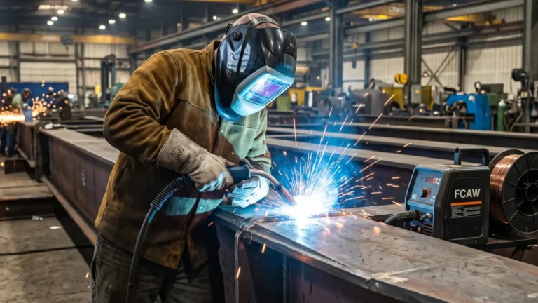
Flux-cored arc welding, commonly known as FCAW, is an arc welding process that uses a continuous tubular electrode. Unlike solid wire, this wire contains an internal flux that performs metallurgical and operational functions during weld bead formation.
This process combines productivity, penetration, and deposition capability, making it suitable for heavy fabrication, steel structures, pipelines, shipyards, and medium- to heavy-thickness industrial components.
Basic principle of the FCAW process
During welding, the electric arc is established between the tubular wire and the base metal. The heat generated melts both materials and forms the weld pool where the joint is created.
As the electrode advances, the filler metal is deposited continuously. This enables a high deposition rate while maintaining excellent performance in welds that require large weld volumes and continuous operation.
Role of the tubular wire and flux
The internal flux helps stabilize the arc, protect the weld pool, and promote slag formation over the weld bead. This slag layer protects the metal while it solidifies.
However, the slag must be properly removed between passes. If it becomes trapped, it can produce internal slag inclusions that compromise joint strength and increase the risk of rejection during inspection.
How the FCAW process works
The FCAW process begins when the tubular wire is continuously fed through the welding gun. As it comes into contact with the base metal, an electric arc is generated, producing the heat required to melt both the electrode and the edges of the joint.
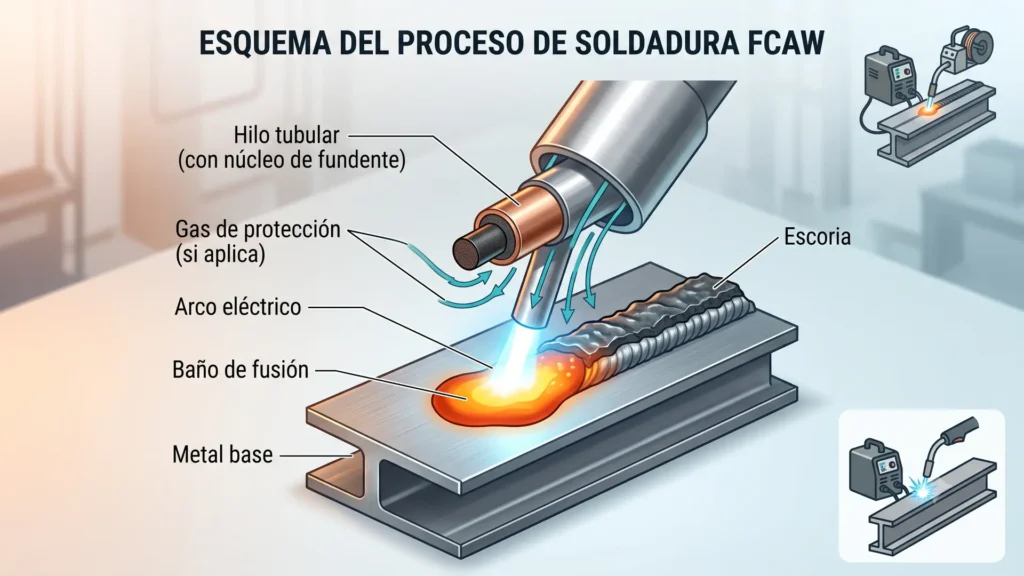
The joint is formed when the molten filler metal from the electrode and the molten base metal mix in the weld pool. As it solidifies, the weld pool forms the weld bead, whose quality depends on arc stability and proper process control.
Arc and weld pool formation
During welding, the internal flux protects the molten weld pool and contributes to slag formation. This protection helps reduce atmospheric contamination and promotes more controlled solidification.
In gas-shielded processes, the external shielding gas complements this function. In self-shielded processes, the flux plays a more critical role, making the operator’s technique even more important.
Variables affecting weld quality
Current, voltage, travel speed, stick-out, and welding gun angle influence penetration, weld bead profile, and the likelihood of internal discontinuities.
When these variables are not properly controlled, lack of fusion, slag inclusions, porosity, or interpass defects may occur. Therefore, FCAW productivity must be managed together with clear quality, inspection, and traceability criteria.
Types and advantages of flux-cored arc welding
Flux-cored arc welding is primarily used in two variants: self-shielded FCAW and gas-shielded FCAW. The selection depends on the working environment, material thickness, required productivity, joint type, and the level of quality control required.
Self-shielded FCAW for field applications
Self-shielded FCAW does not require external shielding gas. The internal flux generates the necessary protection during welding, making it ideal for field work, structural erection, exposed structures, and repair applications where wind or mobility makes the use of gas cylinders difficult.
Gas-shielded FCAW
Gas-shielded FCAW uses an external shielding gas to complement the action of the internal flux. It is commonly used in fabrication shops, production lines, heavy-wall components, and applications requiring greater arc stability.
| Variant | Main advantage | Limitation | Typical application |
|---|---|---|---|
| Self-shielded FCAW | Greater portability | Requires greater operational control | Field work, structures, and repairs |
| Gas-shielded FCAW | More stable arc | Depends on external shielding gas | Fabrication shops and heavy manufacturing |
Advantages over other welding processes
Compared to slower manual welding processes, FCAW deposits a greater volume of metal in less time. This productivity provides significant value in structures, storage tanks, pipelines, and shipyards, provided that proper technical control prevents rework and inspection rejections.
Industrial applications
FCAW provides value when medium- and heavy-thickness components must be joined with high productivity. Consequently, it is widely used in industries where fabrication time, joint strength, and operational continuity are critical factors.
- Construction and infrastructure: Bridges, skyscraper structural beams, and high-voltage transmission towers.
- Energy, oil and gas: Storage tanks, pressure vessels, distillation towers, and components for hydroelectric and wind power plants.
- Mining and heavy equipment: Mining truck chassis, hoppers, excavators, and industrial mills.
- Marine industry: Ship hulls, offshore platforms, and piers.
Discontinuities that compromise weld quality
Flux-cored arc welding offers high productivity, but it can generate discontinuities if process variables, interpass cleaning, or the operator’s technique are not properly controlled.
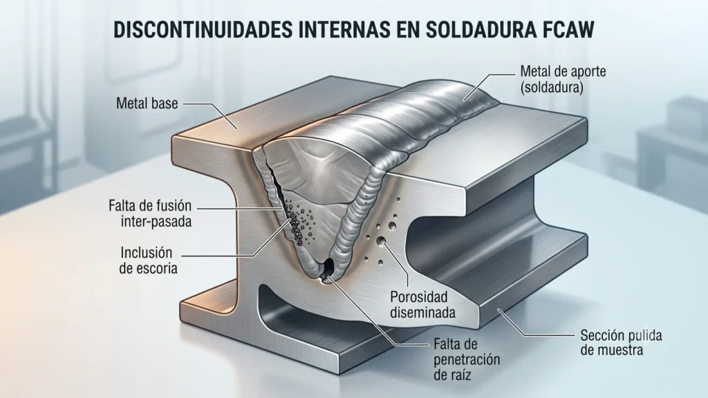
An FCAW weld may appear acceptable on the surface while still containing internal indications capable of affecting the joint’s strength, service life, or technical acceptance.
| Discontinuity | How it occurs | How to prevent it | Why it matters |
|---|---|---|---|
| Lack of fusion | The filler metal fails to fuse properly with the base metal or previous weld passes due to insufficient heat input, incorrect gun angle, or excessive travel speed. | Adjust current, voltage, and travel speed; control the welding gun angle and ensure proper joint preparation. | It can act as a stress concentrator in components subjected to load, pressure, or vibration. |
| Lack of penetration | The joint root does not fuse completely because of insufficient welding parameters, improper root opening, or inadequate welding technique. | Verify joint design, root opening, heat input, and welding sequence according to the qualified procedure. | It reduces the effective strength of the welded section and may lead to rejection under applicable code requirements. |
| Slag inclusions | Flux residues become trapped between weld passes due to poor cleaning, complex joint geometry, or improper electrode manipulation. | Mechanically clean each weld pass, control welding technique, and avoid bead profiles that hinder slag removal. | They create internal discontinuities that reduce weld homogeneity and may require repair. |
| Porosity | Cavities form due to moisture, contamination, inadequate weld pool protection, improper shielding gas, or variations in welding technique. | Keep consumables dry, clean the base metal, control the shielding gas, and avoid drafts when using FCAW-G. | It may compromise weld soundness, especially when clustered or exceeding acceptable limits. |
| Interpass defects | The next weld bead encapsulates slag, irregularities, or residues left from the previous pass. | Visually inspect each weld pass, remove slag, correct irregular bead profiles, and follow the approved welding sequence. | They increase rework, complicate inspection, and affect quality traceability. |
| Cracks | They result from residual stresses, rapid cooling, diffusible hydrogen, improper consumable selection, or inadequate preheating. | Apply preheating when required, control interpass temperature, and use consumables compatible with the base material. | They are critical discontinuities because they can propagate during service and compromise asset integrity. |
In critical applications, the problem is not only that a discontinuity exists. The real risk is that it is not detected, characterized, and evaluated before the welded joint is placed into service.
What does this mean in practice?
In a fabrication shop, industrial plant, or construction project, an FCAW weld may appear uniform, clean, and properly profiled on the surface. However, this does not guarantee that it is free from internal lack of fusion, slag inclusions, porosity, or interpass defects.
Risks to operation and asset integrity
When an internal discontinuity is not detected in time, it may later result in inspection rejection, costly repairs, project delays, or risks to asset integrity. In pipelines, storage tanks, structures, or components subjected to load, pressure, or vibration, an unevaluated indication can become a critical weak point.
For this reason, flux-cored arc welding should not be managed solely from a productivity standpoint. It also requires inspection, quality control, and traceability criteria that verify whether the welded joint meets the project’s technical requirements.
How to inspect critical FCAW welds
To plan the Non-Destructive Testing (NDT) required for inspecting a flux-cored arc welded joint, you must first evaluate the project context, including the joint type, material thickness, equipment criticality, and applicable codes and standards.
It is also important to remember that no single inspection method can detect every type of discontinuity. Therefore, the best practice is to combine surface and volumetric inspection techniques to ensure comprehensive weld evaluation. The most common Non-Destructive Testing methods include:
Visual and surface inspection
Visual inspection evaluates the weld bead profile, undercut, spatter, visible cracks, cleanliness, and surface finish. It may be complemented with liquid penetrant testing or magnetic particle testing when surface-breaking discontinuities must be detected.
Radiographic and ultrasonic testing
To evaluate the internal condition of the welded joint, volumetric methods such as industrial radiography, conventional ultrasonic testing, Phased Array Ultrasonic Testing (PAUT), and Total Focusing Method (TFM) are used. The selected method depends on the joint geometry, the expected orientation of the indication, accessibility, and traceability requirements.
Summary of the most commonly used inspection methods.
| Method | What it evaluates | Main limitation |
|---|---|---|
| Visual inspection (VT) | Weld profile, surface finish, and surface defects | Does not detect internal discontinuities |
| Liquid penetrant testing (PT) | Surface-breaking cracks | Only applicable to discontinuities open to the surface |
| Magnetic particle testing (MT) | Surface and near-surface defects | Requires ferromagnetic materials |
| Radiographic testing (RT) | Porosity, slag inclusions, and volumetric discontinuities | Less effective for planar indications depending on their orientation |
| Ultrasonic testing (UT) | Internal indications | Depends on technique, accessibility, and operator skill |
| PAUT / TFM | Advanced characterization and digital recording | Requires qualified procedures and certified personnelu |
Traceability of the inspection report
In critical applications, inspection involves more than simply detecting an indication. It also requires locating, sizing, documenting, and evaluating it against the acceptance criteria established for the project.
At the following link, you are invited to download the technical checklist for the inspection of critical FCAW welds.
Standards and acceptance criteria for FCAW
In FCAW welds, an indication detected during inspection does not automatically mean that the weld must be rejected. It must first be evaluated according to the applicable code, standard, or project specification.
Understanding the difference between an indication, a discontinuity, and a defect is essential. An indication is a signal observed during inspection; a discontinuity is an interruption in the uniformity of the material; and a defect is a discontinuity that exceeds the acceptance limits established by the applicable code.
ASME, AWS, and API in welding
The applicable standard depends on the asset, industry, and intended service. AWS D1.1 is commonly used for structural steel; API 1104 for pipelines; and ASME Section V serves as a reference for ultrasonic, radiographic, and other non-destructive examination methods.
| Standard or code | Typical application | Contribution to quality control |
|---|---|---|
| AWS D1.1 | Structural steel welds | Defines acceptance and repair criteria |
| API 1104 | Pipeline welding | Establishes acceptance limits for indications in pipelines |
| ASME Section V | Non-destructive testing | Provides examination and inspection methods |
| ASME Section IX | Qualification of welding procedures | Supports qualification of welders and Welding Procedure Specifications (WPS) |
When does an indication become a defect?
An indication becomes a defect when its size, orientation, length, location, or accumulation exceeds the acceptance limits established by the applicable code. Therefore, inspection must provide reliable, traceable, and sufficiently detailed information to determine whether the weld should be accepted, repaired, or rejected.
PAUT and TFM for evaluating high-integrity welded joints
In critical FCAW welds, detecting an indication is not always enough. Inspectors must determine its location, orientation, length, depth, and relationship to the joint geometry in order to assess compliance with project acceptance criteria.
Detection of internal indications
Phased Array Ultrasonic Testing (PAUT) enables weld inspection using multiple beam angles from a single transducer. This improves volumetric coverage and enhances the detection of internal indications such as lack of fusion, lack of penetration, and interpass discontinuities.
Characterization and sizing
The Total Focusing Method (TFM) provides a more detailed representation of an indication, helping inspectors interpret its shape, location, and potential severity. In highly critical welds, this capability reduces uncertainty during technical evaluation.
Digital inspection records
In addition to detecting discontinuities, PAUT and TFM generate digital inspection records. This improves traceability, facilitates audits, and supports well-documented decisions regarding weld acceptance, repair, or rejection.
Sonatest solutions for FCAW weld inspection
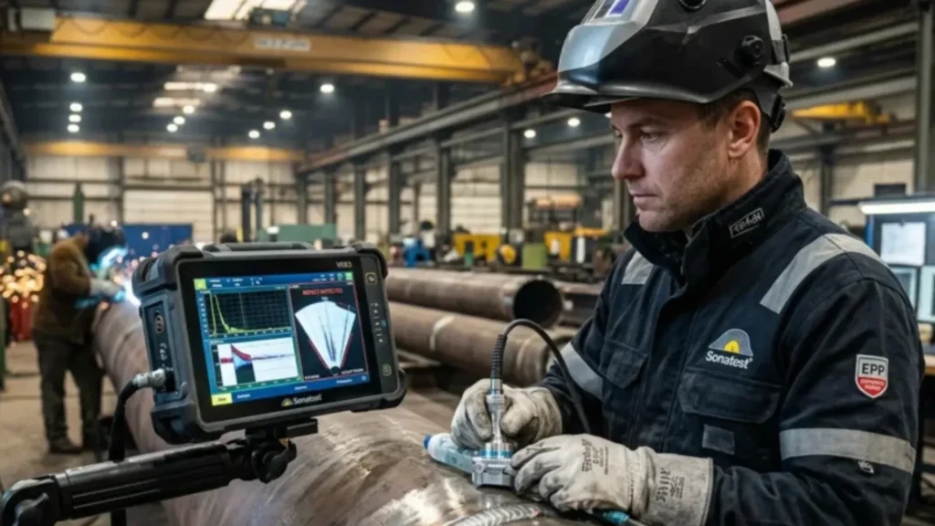
When an FCAW weld is part of a critical asset, inspection must provide more than a simple signal. It must help inspectors interpret, size, and document indications with complete technical traceability.
In this context, Sonatest offers advanced ultrasonic inspection solutions for industrial applications where the reliability of welded joints is critical. These include:
VEO3 for PAUT and TFM
The Sonatest VEO3 supports advanced technologies such as PAUT and TFM, making it ideal for inspecting butt welds, characterizing internal discontinuities, and generating digital inspection records. This robust, portable, and user-friendly PAUT instrument is capable of inspecting long welds quickly and efficiently.
For QA/QC professionals, inspectors, and integrity engineers, these capabilities help reduce uncertainty when making decisions to accept, repair, or reject welded joints.
Wave for ultrasonic inspection
Wave is designed for portable ultrasonic inspections and includes tools that support calibration, signal analysis, and interpretation of indications in both field and workshop environments.
The Sonatest solutions are designed to deliver fast, efficient, and reliable portable inspections. They provide an ideal solution for butt weld inspection in accordance with major international and regional standards.
Thanks to state-of-the-art instrumentation and industry-leading data acquisition and analysis software, these solutions deliver highly reliable results, reduce uncertainty during evaluations, streamline inspection setup, and increase scanning speed, ultimately improving field productivity. In FCAW applications, this means evaluating discontinuities more clearly, supporting technical reports, and making better-informed decisions.
Inspenet TV: Sonatest and PAUT technologies for NDT
To complement this approach, Inspenet TV interviewed Yannis Wallace, Area Sales Manager at Sonatest, during ASNT 2024. The interview explored how PAUT technology and solutions such as VEO3 and Prisma support more accurate inspections in non-destructive testing applications.
The interview also highlights the evolution of technologies such as TFM and TFMi, which are designed to improve the visualization of internal indications and facilitate technical interpretation in industrial applications where inspection reliability is critical.
Need to improve the reliability of your FCAW weld inspections?
Sonatest’s advanced ultrasonic inspection solutions help evaluate critical welded joints using PAUT and TFM technologies, providing digital traceability and supporting informed decisions regarding weld acceptance, repair, or rejection.

Criteria for selecting inspection technology
The selection of an inspection technology should not be based solely on equipment availability. It must respond to the type of weld, material thickness, joint geometry, accessibility, applicable code, and the criticality of the asset.
Thickness, geometry, and applicable code
For thick-section FCAW welds, complex joint geometries, or critical components, the selected inspection technique must provide adequate coverage of the inspection volume. It must also comply with the approved inspection procedure, the applicable standard, and the project’s acceptance criteria.
Productivity and traceability
When inspecting a large number of welds, productivity is also an important factor. However, inspection speed must be accompanied by clear records, verifiable data, and comprehensive reports that support decisions regarding weld acceptance, repair, or rejection.
Conclusion
Flux-cored arc welding provides productivity, versatility, and high performance for demanding industrial applications. However, its true value depends on proper process control, the prevention of discontinuities, and reliable verification of the welded joint. In projects where weld quality directly affects safety, operational performance, and asset integrity, combining FCAW best practices with advanced inspection technologies makes it possible to achieve more productive, reliable, and inspectable welded joints.
References
- American Petroleum Institute. (2021). API Standard 1104: Welding of pipelines and related facilities (22nd ed.). American Petroleum Institute.
- American Society of Mechanical Engineers. (2025). BPVC Section V: Nondestructive examination. ASME.
- American Society of Mechanical Engineers. (2025). BPVC Section IX: Welding, brazing, and fusing qualifications. ASME.
- American Welding Society. (2025). AWS D1.1/D1.1M:2025: Structural welding code, Steel. American Welding Society.
- International Organization for Standardization. (2018). ISO 17640:2018: Non-destructive testing of welds, Ultrasonic testing, Techniques, testing levels, and assessment. ISO.
- Sonatest. (n.d.). Applications & solutions: Weld inspection. Sonatest.
- Sonatest. (n.d.). PAUT butt weld inspection utilising the VEO3. Sonatest.
- Sonatest. (n.d.). TFM and TFMi for butt weld inspection and defect characterisation. Sonatest.
- Sonatest. (n.d.). Ultrasonic butt weld inspection with the Wave. Sonatest.
Frequently asked questions (FAQs)
What is FCAW welding?
FCAW is an arc welding process that uses a tubular wire with an internal flux to form and protect the weld bead.
What is the difference between FCAW-S and FCAW-G?
FCAW-S is self-shielded and does not require external shielding gas. FCAW-G uses shielding gas to improve arc stability and weld quality.
What defects can occur in FCAW welds?
Common discontinuities include lack of fusion, lack of penetration, slag inclusions, porosity, cracks, and interpass defects.
How is an FCAW weld inspected?
An FCAW weld is inspected using visual, surface, and volumetric non-destructive testing methods, including radiographic testing (RT), conventional ultrasonic testing (UT), Phased Array Ultrasonic Testing (PAUT), and the Total Focusing Method (TFM).