Table of Contents
- Fluid transfer systems and marine spill risk
- Marine loading arm and operating envelope
- ESD System: Motor operated valve and pressure surges
- ERS and emergency release coupler
- OCIMF MLA4 and API 2610 at marine terminals
- COTESO Group: Transfer solutions for marine terminals
- Conclusions
- References
- Frequently Asked Questions (FAQs)
During a ship-to-terminal transfer, the connection point is exposed to changes in vessel draft and tide, as well as surge and sway motions. The marine loading arm must accommodate these movements within a defined operating envelope to maintain leak-tightness throughout product transfer.
When the relative movements between the vessel and the terminal exceed the loading arm’s design limits, additional mechanical loads may be imposed on its components, swivel joints, and connection to the ship’s manifold, increasing the risk of loss of containment.
Spill prevention depends on the coordinated response of position monitoring, the ESD system, isolation valves, and the Emergency Release System (ERS). Under an unsafe condition, the ESD must first stop the transfer and initiate product isolation before the ERS performs the emergency release, when required.
Fluid transfer systems and marine spill risk
A terminal’s fluid transfer systems connect a fixed installation to a vessel whose position changes continuously. The design basis must consider the location of the ship’s manifold, tidal range, vessel dimensions, pressure, temperature, flow rate, product properties, and environmental loads.
Unlike Ship-to-Ship (STS) transfers, where product is transferred directly between two vessels using hoses and specialized mooring arrangements, the ship-shore interface at a terminal may incorporate marine loading arms connected to a fixed installation.
Loss of containment may occur at swivel joints, seals, connections, valves, or during a disconnection while product is still flowing. The operating envelope defines the area within which the equipment can move without exceeding its operating limits.
OCIMF guidance includes sensors or limit switches associated with the vertical and horizontal limits of the marine loading arm. These devices may initiate a shutdown following an unacceptable excursion or certain losses of power. The limits must provide sufficient time for the ESD to stop the transfer before the emergency release condition is reached.
Marine loading arm and operating envelope
A marine loading arm uses rigid articulated piping and swivel joints to establish the connection between the terminal piping system and the ship’s manifold. The arm geometry must accommodate the expected vessel movements without transferring loads that are incompatible with its structure, the connection, or the associated piping.
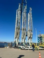
Figure 1. Marine loading arms installed at a terminal,
showing articulated systems and process connections
for fluid transfer.
Source: COTESO Group.
OCIMF MLA4, Fourth Edition, published in 2019, establishes criteria for the design and procurement of Marine Loading Arms and covers applications, products transferred, operating envelope, manifold spacing, jetty and piping configuration, maintenance, and different loading arm configurations.
Swivel joints provide articulation while keeping the product contained. KANON states that these components are subjected to axial and bending loads associated with loading arm reach and wind forces. For chemical service, the manufacturer specifies carbon steel, duplex, SS304L, and SS316L, pressure ratings of 150#, 300#, 600#, and 900#, and operating temperatures ranging from -198 to +230 °C, depending on the configuration.
The ship connection may incorporate a Hydraulic Quick Connect/Disconnect Coupler (QC/DC) for normal connection and disconnection of the loading arm at the vessel manifold.
This should not be confused with the emergency release coupler. The QC/DC is intended for normal operating connection and disconnection, whereas the emergency release device acts when remaining connected presents a risk.
ESD System: Motor operated valve and pressure surges
The Emergency Shutdown System must bring the transfer operation from its normal operating condition to a defined shutdown and isolation condition. The logic may act on pumps and valves located both onboard the vessel and ashore, making ship/shore coordination an important factor in the response of the overall system.
A motor-operated valve may form part of this function, but electric actuation alone does not determine its suitability for emergency shutdown service. Differential pressure, required torque, valve stroke time, position feedback, available power supply, and the expected response to loss of power must all be evaluated.
Valve closure time is directly related to line hydraulics. A rapid reduction in product velocity generates a pressure surge whose magnitude depends on product velocity, line length and elasticity, and valve closure time. Closing a valve as quickly as possible does not always represent the safest operating condition.
OCIMF describes configurations incorporating surge relief systems that can divert liquid flow to a surge drum while the ESD and ERS isolation valves are closing. The trapped volume between the isolation valves and the separation point must also be evaluated because it determines the amount of product that could potentially be released.
The ESD system requires verification of line hydraulics, valve locations, actuation times, interlocks, position feedback, and response to loss of power before the final shutdown sequence is established.
ERS and emergency release coupler
The ERS acts when stopping the transfer alone is no longer sufficient to maintain a safe connection between the vessel and the oil terminal.
In the ERS configuration incorporating a Powered Emergency Release Coupling (PERC) described by OCIMF, the sequence includes ESD activation, ERS activation, closure of the ERS valves, PERC activation, and automatic disconnection of the loading arm.
Manufacturer terminology may vary. KANON refers to the Emergency Release Coupler (ERC) as a device within its Emergency Safety Systems (ESS) designed to provide automatic disconnection when the limits of the loading arm’s safe working envelope are exceeded.
ERC and ERS are not the same. The ERC is the emergency release coupler that physically performs the separation, whereas the ERS is the system or function that controls the release, including product isolation and the actuation sequence.
For the disconnection to effectively minimize spillage, the associated valves must close before the two halves of the coupler separate. The distance between these valves and the separation plane also affects the residual product volume.
Verification must therefore be performed at system level. A valve may successfully complete an individual test and an ERC may operate mechanically, but this does not demonstrate that position detection, ESD, isolation, and emergency release will respond in the required sequence and within the specified times during an actual transfer operation.
OCIMF MLA4 and API 2610 at marine terminals
OCIMF MLA4 is specifically intended for the design and procurement of Marine Loading Arms and defines information related to geometry, transferred products, operating envelope, interfaces, and equipment configuration.
API Std 2610 covers the design, construction, operation, maintenance, and inspection of marine terminal and tank facilities. API lists the Fourth Edition, dated March 2026.
API 2610 does not replace MLA4 as the loading arm specification. For the specific coordination between emergency shutdown and emergency disconnection, the OCIMF publication Linked Ship/Shore Emergency Shutdown Systems for Oil and Chemical Transfers is also applicable.
COTESO Group: Transfer solutions for marine terminals
Within the fluid transfer sector, COTESO Group supplies and integrates equipment for gases, liquids, chemicals, and hydrocarbons. Its Industrial Supply Division includes valves, hoses, piping and fittings, sealing solutions, and loading arms.
In the marine segment, COTESO works with KANON Loading Equipment, a manufacturer specializing in Marine, Rail, and Road liquid transfer systems. The relationship includes distribution, installation, and technical service for Marine Loading Arms, with exclusive representation in Panama and Chile.
Marine loading arms and isolation components
COTESO’s Marine Loading Arm solutions can be configured according to the transferred product, pressure, temperature, transfer diameter, ship manifold geometry, expected vessel movements, and the terminal’s emergency shutdown philosophy.
The following Inspenet TV video presents KANON Loading Equipment’s approach to liquid transfer systems, the role of loading arms, and the importance of swivel joints and sealing in maintaining leak-tight performance during transfer operations.
The system may incorporate swivel joints, hydraulic actuation, Quick Connect/Disconnect Couplers (QC/DC), operating-envelope monitoring, and emergency release devices coordinated with the isolation valves and ESD/ERS logic.
The valve portfolio includes ball, gate, globe, check, and butterfly valves, as well as motor-operated valves, low-emission valves, and special-material configurations. When a valve performs an ESD function, its selection must consider differential pressure, actuator torque, closure time, position feedback, fail-safe condition, and compatibility with the transferred fluid.
A valve that closes correctly during an individual test may still produce an unsuitable system response if its actuation time is not consistent with the flow rate, line volume, and pressure-surge control strategy defined for the terminal.
Overhaul, testing, and commissioning
Seals, swivel joints, hydraulic systems, connections, and safety devices are subjected to movement, mechanical loads, and repeated operating cycles. Their functional capability must therefore be verified during maintenance.
One documented case involved the dismantling and transport of a KANON Marine Loading Arm installed at ENAP’s San Vicente Marine Terminal in Chile for an overhaul at the manufacturer’s facilities in the Netherlands.
An intervention of this type allows inspection of piping, swivel joints, seals, and mechanical components, replacement of deteriorated items, and subsequent verification of the complete assembly through a Factory Acceptance Test (FAT).
Verification continues through installation and commissioning. COTESO’s technical supervision services include site inspection and supervision, quality control, technical audits, pre-commissioning, system integration, performance testing, commissioning, and handover support.
Within an ESD/ERS system, these activities make it possible to verify that position signals, valves, actuators, alarms, interlocks, and emergency release devices respond according to the intended sequence. Functional acceptance must confirm that the system can transition from normal transfer to isolation and, when required, to emergency release without losing control of the product.
Do you need information on loading arm and fluid transfer solutions for marine terminals? Visit the COTESO profile on Inspenet Corporate to review its company information, portfolio, and contact channels.
Conclusions
During a marine transfer operation, the marine loading arm must accommodate the expected vessel movements without exceeding its operating envelope. If an abnormal condition develops, the system must provide sufficient margin to stop the transfer and complete product isolation before physical disconnection becomes necessary.
This margin depends on ESD response time, valve closure, the hydraulic behavior of the line, and the volume of product contained between the isolation points and the emergency release coupler.
The capability of the ERS, therefore, cannot be assessed solely by confirming that the ERC can disconnect. During an emergency, what matters is that the flow has already stopped, the valves have reached their required positions, and the volume remaining close to the separation point remains within the limits established by the system design.
References
- OCIMF. Design and Construction Specification for Marine Loading Arms (MLA4), Fourth Edition, 2019.
- OCIMF. Linked Ship/Shore Emergency Shutdown Systems for Oil and Chemical Transfers.
- American Petroleum Institute. API Std 2610 — Design, Construction, Operation, Maintenance and Inspection of Terminal and Tank Facilities, Fourth Edition, 2026.
- KANON Loading Equipment. Marine Loading Arms: Chemicals.
- COTESO Group. Publication on the partnership with KANON Loading Equipment and the distribution of Marine Loading Arms in Panama and Chile. 2025.
Frequently Asked Questions (FAQs)
What is the function of a marine loading arm?
A marine loading arm connects the terminal piping system to the ship’s manifold through rigid articulated piping and swivel joints. Its geometry allows it to accommodate the expected vessel movements within the operating envelope defined for the installation.
What is the difference between an ERC and an ERS?
The ERC (Emergency Release Coupler) is the device that physically performs the disconnection. The ERS (Emergency Release System) is the system that coordinates the emergency release, including prior product isolation and actuation of the coupler.
Why must the ESD act before the ERS?
Because the transfer must be stopped and the product isolated before the loading arm is disconnected. OCIMF establishes this sequence to minimize spillage during an emergency disconnection.
Is API 2610 the design standard for a marine loading arm?
No. API 2610 broadly addresses terminal and tank facilities. For the design and procurement of Marine Loading Arms, the specific OCIMF publication is MLA4, Fourth Edition, 2019.