Table of Contents
- Why offshore chain wear requires metrology
- Mooring chain inspection: What should be measured?
- What limits caliper measurement in the splash zone?
- 3D photogrammetry for contactless chain measurement
- What must be validated before accepting 3D measurements?
- From the 3D model to an integrity decision
- Conclusions
- Frequently Asked Questions
- References
Mooring chains can remain structurally continuous while still having lost enough cross-section or geometry to alter their response to cyclic loading. Therefore, during mooring chain inspection, it is important to record the remaining cross-section, identify areas of concentrated wear, and track damage progression between inspection campaigns.
Inspection requirements become more stringent in the splash zone and in subsea segments, where corrosion, pitting, interlink wear, deformation, and fatigue may act simultaneously. Measurements must therefore be repeatable and traceable to compare the actual condition of the chain against its reference geometry.
Why offshore chain wear requires metrology
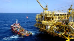
Mooring lines maintain the position of FPSOs, platforms, and other floating units used in offshore exploration and production operations under the combined action of wind, waves, and current. Loss of integrity in one component can reduce the capacity of a mooring line and require reassessment of loads, redundancy, and the system’s operating conditions.
ISO 19901-7:2026 covers the life cycle of stationkeeping systems, including configuration, installation, post-installation surveys, and as-installed assessments for integrity management. API RP 2MIM also establishes integrity management practices for mooring systems used on permanent floating production installations.
In service, both geometry and visual condition must be considered. Uniform corrosion reduces cross-section; pitting creates local stress concentrations; interlink contact produces localized wear; and cyclic loading drives fatigue mechanisms.
At SPM terminals, chafe chains associated with vessel mooring are also exposed to wear and corrosion during service. Their dimensional condition therefore forms part of the integrity management of the mooring system.
In areas near fairleads, chain hawses, or chain stoppers, pretension, the angle between links, and friction can restrict articulation and induce out-of-plane bending (OPB). This mechanism creates local stress concentrations and can increase fatigue damage in the affected links.
For this reason, offshore chain wear should be documented using dimensional data capable of distinguishing an actual change from the inherent scatter of the measurement method.
Mooring chain inspection: What should be measured?
Mooring chain inspection may include bar diameter, inter-grip length, link deformation, and geometric variations in areas subject to greater exposure. The location and number of measurements depend on the design and the integrity management program.
Bar diameter measurements quantify cross-sectional loss at defined locations. Inter-grip length helps verify changes in the relative geometry between adjacent links. Contact areas, the crown, weld side, pitted surfaces, and any indication of deformation or abnormal wear should also be examined.
An isolated measurement loses value if it cannot be located on the same chain link and in the same area during the next campaign. For degradation tracking, traceability should identify the mooring line, chain link, orientation, measurement plane, date, method, calibration, and measurement uncertainty.
Two questions should also be considered separately: how much the geometry has changed and whether there are indications requiring specific NDT methods. Dimensional metrology quantifies material loss, wear, and deformation, but it does not replace techniques intended to detect cracks or discontinuities when required by the integrity program.
What limits caliper measurement in the splash zone?
Mechanical calipers remain a valid tool for dimensional control. Their limitation becomes apparent when a complex geometry is characterized using only a limited number of discrete contact points.
For large-diameter mooring chain, small differences in orientation, position, and measurement plane can affect the result. Access also influences data acquisition: rope access may be required in the splash zone, while underwater the ROV must position and manipulate the tool against the chain link.
When the surface is irregular because of corrosion or wear, reproducing exactly the same measurement location during successive campaigns introduces another variable. This is particularly relevant when comparing small dimensional changes between inspections.
In a field study published by Abyss, the uncertainty analysis for caliper measurements considered intrinsic tool error, angular deviations, and offsets in measurement position. For the procedure analyzed, the cumulative estimate was approximately 2%. This value is provided for reference and depends on the measurement procedure used.
How can a mooring chain be inspected in the splash zone?
The inspection begins by identifying the target mooring line and chain links, followed by surface preparation and definition of the areas to be measured. In the splash zone, rope access may be used when permitted by the installation configuration.
With optical metrology, data are acquired without placing a tool directly on every measurement point. Geometry is captured from controlled positions, and dimensional measurements are subsequently extracted from the 3D reconstruction.
The validity of these measurements depends on whether coverage, calibration, traceability, and uncertainty meet the criteria established for the inspection procedure.
| Aspect | Mechanical caliper | Optical 3D metrology |
|---|---|---|
| Measurement type | Contact measurement at discrete points | Reconstructed 3D surface |
| Access | The tool must physically reach the measurement point | Optical capture from defined positions |
| Repeatability | Requires reproducing the same point, plane, and orientation | The model allows the geometry to be revisited |
| Record | Point dimensional value | Geometry, imagery, and associated dimensional data |
| Main limitation | Spatial coverage and field execution | Calibration, visibility, coverage, and validation |
This comparison does not mean that calipers should automatically be replaced. In mooring chain inspection, any alternative must demonstrate that its uncertainty, repeatability, and procedure are suitable for the integrity decision being made.
3D photogrammetry for contactless chain measurement
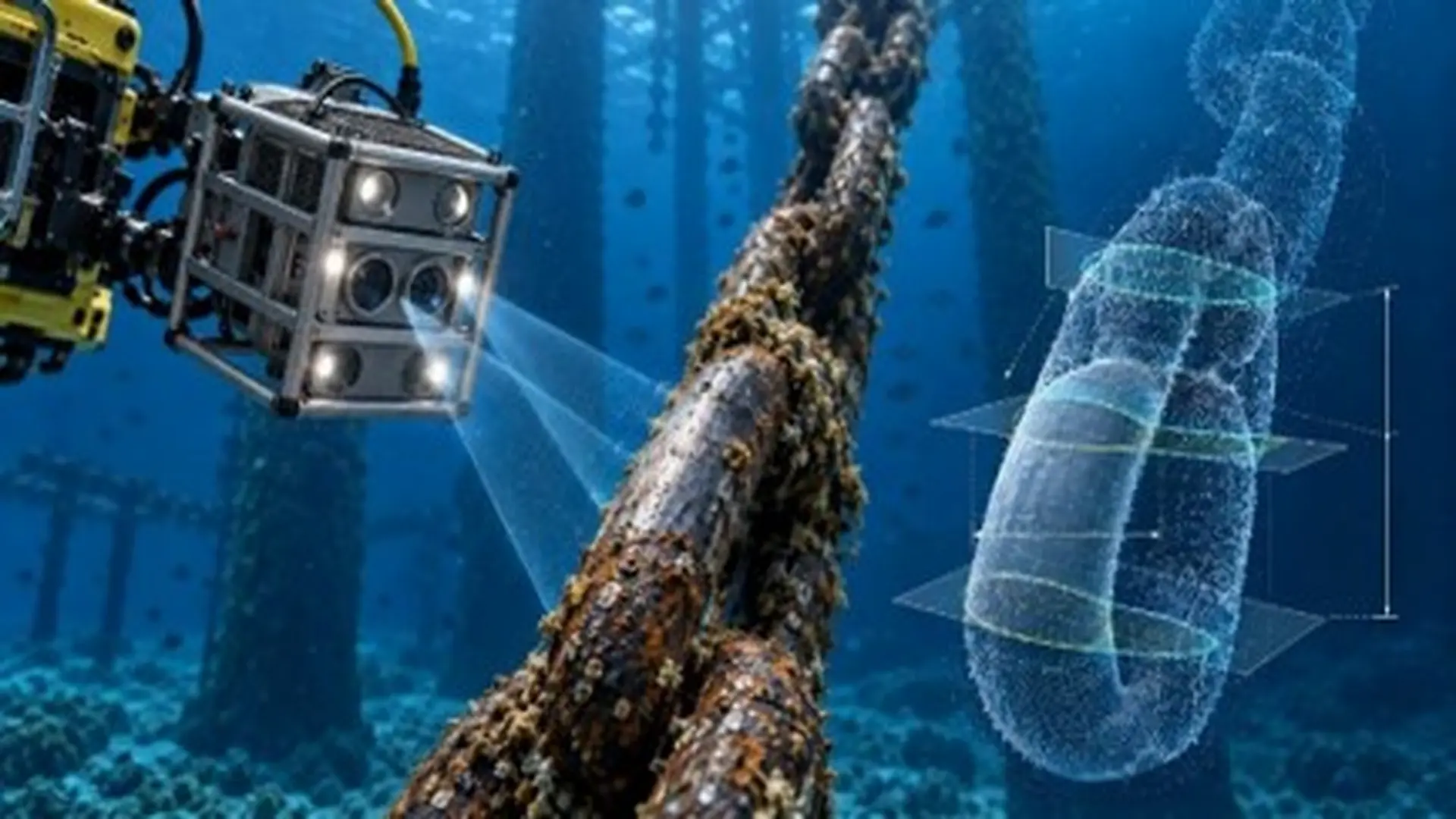
Stereoscopic 3D photogrammetry uses two calibrated cameras with a known geometric relationship. When the same surface point appears in both images, image disparity can be used to triangulate coordinates and reconstruct the three-dimensional surface.
Systematic acquisition from different angles generates a 3D model of the chain link. Axes can then be defined on the reconstruction, sections created at predetermined positions, and dimensional measurements extracted along the same planes established in the inspection procedure.
Unlike a conventional photograph, the reconstruction contains metric information that can be revisited later. This allows different dimensions to be obtained from the model without physically positioning a caliper at every measurement point.
Because the measurement is contactless, optical data acquisition can reduce point-by-point mechanical manipulation of the chain link during an inspection campaign. It does not eliminate the need for access, cleaning, or proper system positioning, but it reduces dependence on repeatedly placing and reorienting a contact tool on the chain.
For subsea inspection, calibration requires additional controls because the optical path passes through water and the system’s optical ports. Working distance, lighting, turbidity, focus, and stability all influence reconstruction quality.
3D photogrammetry also does not eliminate the need for surface preparation when marine growth, deposits, or corrosion products obscure the metallic geometry. A high-resolution reconstruction can only reliably measure the surface that is adequately exposed.
What must be validated before accepting 3D measurements?
The nominal accuracy of a camera alone does not define the quality of a 3D metrology campaign. The complete procedure must demonstrate performance under the actual geometry, working distance, and operating environment.
Validation should cover system calibration, procedure uncertainty, coverage of the measured surfaces, unambiguous identification of the mooring line and chain link, reconstruction quality, traceable dimensional references, preservation of original data, and compatibility with operator requirements and the applicable classification society.
Repeatability is especially important. A difference of 1 mm between two campaigns can only be interpreted as wear when the combined uncertainty is low enough to resolve that change. If the variation remains within the uncertainty of the procedure, it should not be interpreted as actual material loss.
Lantern Eye™: 3D metrology in splash zone and subsea environments
Abyss Solutions developed Lantern Eye™, its visual 3D metrology system based on stereo imagery for generating three-dimensional reconstructions and performing contactless measurements on offshore assets.
The company’s documentation distinguishes configurations according to the inspection environment. Lantern Eye™ Air (LEA) is designed for inspections in air and in the splash zone and can be deployed using rope access. For subsea environments, Lantern Eye™ S (LES) can be integrated with an ROV to capture stereo imagery of the components being inspected.
The following video shows the subsea application of Lantern Eye™ integrated with an ROV for optical data capture and 3D model generation.

The current Lantern Eye page states that the technology has ABS approval. For subsea mooring chain inspection, Abyss specifically documents Lantern Eye™ S as an ABS class-certified solution.
In the specific case of Lantern Eye™ Air, Abyss published an inspection campaign conducted in the splash zone on chain links A through E of mooring lines 1, 2, 4, and 5. The procedure included bar diameter measurements, inter-grip length, and dimensional measurements at different planes and positions on the chain link.
The 3D metrology bar diameter measurements were within 1.7% of the caliper measurements at 2σ (95% confidence), while the cumulative difference for inter-grip length was 0.9%. The validation procedure placed the expected uncertainty of the 3D measurements at approximately 1%.
These values correspond to a specific inspection campaign and should not be automatically extrapolated to other diameters, geometries, water conditions, or data acquisition configurations. Their value lies in demonstrating a methodology capable of preserving the geometry associated with each measurement and improving comparison between campaigns.
When an inspection campaign requires improved dimensional repeatability, reduced dependence on contact measurements, or comparison of the same chain link across successive inspections, the scope can be defined with Abyss Solutions according to the areas to be measured, required accuracy, access conditions, and integrity deliverables.
From the 3D model to an integrity decision
3D geometry has engineering value when it is related to cross-sectional loss, damage location, and component history. This information can support fatigue analyses, mechanical assessments, and life-extension decisions, provided that the procedure preserves the required metrological traceability.
DNV documents the use of 3D laser scanning of recovered chains to establish the exact geometry of test samples and extract dimensions as part of life-extension assessments, together with fatigue testing, breaking-load testing, mechanical property testing, and examination of corrosion and wear.
Conclusions
Determining the condition of a chain requires demonstrating that the observed dimensional change exceeds the uncertainty of the measurement method and actually corresponds to material loss, deformation, or geometric variation. In this process, mooring chain inspection must preserve spatial reference, traceability, calibration, and consistent criteria for comparison between campaigns.
3D metrology adds value when each dimension remains linked to the actual geometry of the chain link and can be revisited later. This dimensional basis supports decisions on monitoring, complementary NDT, mechanical assessment, or intervention when the measured variation exceeds the uncertainty of the procedure.
Frequently Asked Questions
How can 3D metrology reduce handling during an inspection campaign?
Optical data acquisition extracts dimensions from a 3D reconstruction without placing a caliper at every measurement point. This reduces repetitive mechanical handling, although access, surface preparation, and proper system positioning are still required.
How can wear be measured without relying exclusively on calipers?
3D photogrammetry reconstructs the surface of the chain link and allows diameters, lengths, and geometric changes to be obtained from a metric 3D model. Calipers may still be used as a reference or verification method when required by the procedure.
How can repeatable measurements be obtained between campaigns?
The mooring line and chain link identification, orientation, measurement areas, calibration, procedure, and uncertainty must be preserved. A 3D model also allows the geometry used for each measurement to be relocated and reviewed later.
How can one inspection be compared with the next?
Comparison requires an initial dimensional reference and traceable data from successive campaigns. A variation should only be interpreted as wear when it exceeds the uncertainty of the measurement method and corresponds to the same area of the component.
References
- ISO 19901-7:2026. Specific requirements for offshore structures – Part 7: Stationkeeping systems for floating offshore structures and mobile offshore units.
- API RP 2MIM. Mooring Integrity Management.
- Abyss Solutions. Lantern Eye and mooring chain inspection case study using a stereo imaging system.
- DNV. Technical documentation on life-extension assessment of recovered chains using 3D geometry, mechanical testing, and fatigue testing.