In mining operations, slurry pumps are among the most widely used rotating assets and, at the same time, among the most underestimated in reliability programs.
Unlike a conventional centrifugal pump that handles clean liquids, a slurry pump transports a heterogeneous mixture of solids suspended in a liquid, ranging from flotation tailings to concentrated mineral slurry, under conditions of abrasion, high solids concentration, and variable flow regimes that rarely match the original design point.
This guide is intended for rotating equipment and process engineers who need to accurately distinguish these failure modes and act on the root cause rather than merely addressing the symptom. The cost of failing to do so is significant: a catastrophic bearing failure in a large, critical slurry pump can result in a plant shutdown lasting more than 72 hours, with production losses amounting to millions of dollars, depending on the operation.
What is a slurry pump and what is its purpose?
A slurry is a mixture of solids suspended in a carrier liquid, generally water. In mining, the purpose of a slurry is to enable the hydraulic transport of ore, concentrate, or tailings through pipelines, avoiding costly mechanical handling while allowing continuous processing in grinding, flotation, thickening, and tailings disposal circuits.
A slurry pump is therefore the rotating equipment specifically designed to transport this abrasive, high-density mixture without allowing premature wear or hydraulic performance losses to compromise plant availability.
Low-concentration slurries (less than 10% solids) behave hydraulically in a manner similar to water. Medium-to-high concentration slurries (10% to 50%), typical of flotation tailings and mineral pulp, require minimum transport velocities to prevent sedimentation. Dense slurries (greater than 50%, such as filter press discharges) require side-suction designs and intermittent-duty pumps capable of handling semi-solid pastes.
This classification is not merely an academic distinction; it directly determines pump selection. A pump designed for low solids concentration (low Cw) installed in a high solids concentration (high Cw) service will fail prematurely because of accelerated wear at the impeller eye and the throatbush (suction throat bushing), even if the rest of the hydraulic engineering is correct.
Therefore, the first question that any slurry pump failure analysis should answer is not, “What broke?” but rather, “Does the selected pump match the actual slurry being transported today, rather than the slurry it was designed for five years ago?” It is common for process conditions, mineralogy, ore hardness, and d90 particle size to change over time without the equipment specification being updated accordingly.
What are the types of slurry pumps?
Slurry pumps are primarily classified according to their hydraulic configuration and shaft sealing mechanism, two variables that directly determine their resistance to abrasion and their service life in mining applications. Based on hydraulic configuration, they include:
- The most common in mining are horizontal end-suction centrifugal pumps with semi-open or closed impellers (the dominant configuration in grinding and tailings circuits).
- Side-suction pumps for dense paste slurries (commonly used in filter press discharge applications), and vertical sump pumps for collection pits and sumps.
Each configuration is designed for a specific combination of total dynamic head (TDH), particle size, and intermittent or continuous operating conditions. A centrifugal expeller, for example, creates a low-pressure zone that repels solids away from the seal through centrifugal force, largely eliminating the need for seal water. However, it requires accurately controlled axial clearance to maintain its effectiveness.
Double mechanical seals, on the other hand, completely isolate the sealing interface from the slurry, achieving virtually zero visible leakage, although they require a pressurized barrier fluid system that must be monitored independently.
Regarding metallurgy, the choice between high-chrome liners and elastomer liners (natural rubber or polyurethane) depends on the balance among particle size, slurry pH, and impact velocity.
High-chrome alloys provide superior resistance to sliding abrasion caused by fine particles but are brittle under impacts from coarse particles. Rubber liners absorb the impact of large particles more effectively through elastic deformation, but they deteriorate under high temperatures or when handling slurries containing hydrocarbons. This material selection should be reviewed whenever the feed mineralogy changes, not only during the original project design.
Failure diagnosis: vibration, cavitation, and clogging
The starting point for any slurry pump failure diagnosis is verifying whether the equipment is operating close to its Best Efficiency Point (BEP).
Sustained operation outside the BEP, either below 70% or above 110% of the design flow rate, is the underlying root cause of the three primary failure modes affecting this type of equipment, even when the immediate symptom appears to be purely mechanical.
1. Vibration: Vibration caused by misalignment, imbalance, or bearing wear is predominantly manifested at 1X running speed, with stable and repeatable amplitude.
Vibration associated with cavitation, however, exhibits a broadband signature, with energy typically distributed between 2 kHz and 20 kHz, accompanied by the characteristic sound field technicians often describe as “gravel rolling” inside the volute.
Vibration caused by internal recirculation, common when the pump operates well below the BEP, produces low-frequency pulsations in the suction zone, with the characteristic “vortex” erosion pattern on the impeller faces becoming visible during the next major inspection.
2. Cavitation: Cavitation occurs when the local pressure at the pump suction falls below the vapor pressure of the fluid, forming vapor bubbles that violently collapse upon reaching higher-pressure regions, typically just downstream of the impeller eye and on the vane surfaces.
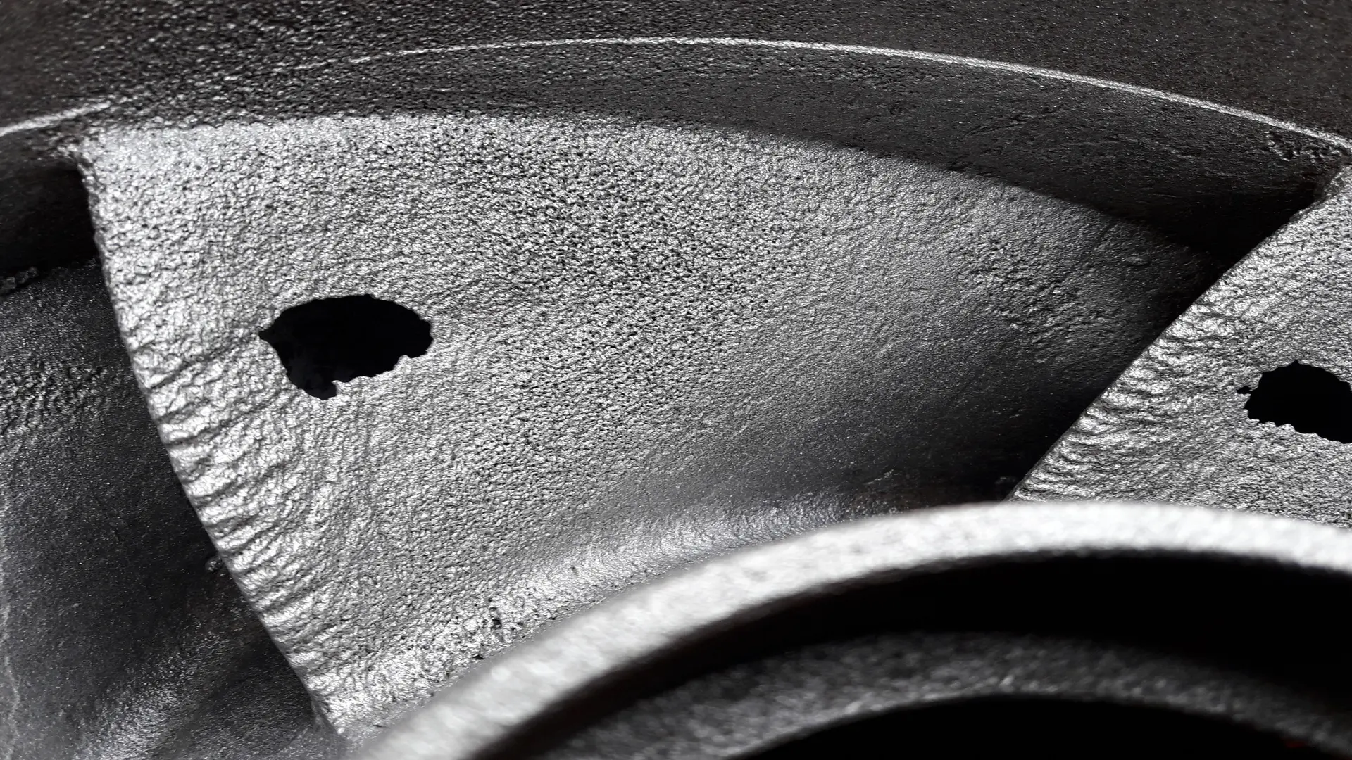
This collapse generates progressive pitting that can transform the impeller surface into a sponge-like texture within only a few weeks of severe operation. The simultaneous drop in discharge pressure, combined with increased broadband vibration and the characteristic gravel-like noise, forms the classic field diagnostic triad for cavitation.
3. Clogging: Clogging occurs when the slurry transport velocity drops below the critical settling velocity, generally between 2.5 and 4.0 m/s for typical mining slurries, allowing solids to settle at the bottom of the pipeline or accumulate in low-velocity areas inside the volute.
The earliest warning sign is usually a gradual increase in discharge pressure accompanied by a reduction in measured flow rate, a pattern that clearly differs from the simultaneous decrease in pressure and flow that characterizes cavitation.
How to prevent cavitation in slurry pumps?
Preventing cavitation in slurry pumps is based on maintaining a sufficient margin between the Net Positive Suction Head Available (NPSHa) in the system and the Net Positive Suction Head Required (NPSHr) by the pump. This relationship becomes more complex in mining applications because the effective NPSHr of a slurry pump increases with solids concentration and impeller wear, unlike clean-water pumps, whose NPSHr remains relatively stable throughout their service life.
The difference between factory test conditions and actual site conditions—including elevation, slurry temperature, and the length and configuration of the suction piping—is, in fact, one of the most common causes of cavitation in pumps that were “correctly” specified on paper.
The most effective corrective actions include lowering the pump relative to the suction liquid level whenever feasible, increasing the diameter of the suction pipe to reduce friction losses, minimizing the number of elbows and valves upstream of the suction, and avoiding suction-line throttling under any circumstances (unlike the discharge line, where throttling may be temporarily used to reduce flow rate and, consequently, the NPSHr).
In systems equipped with variable frequency drives (VFDs), adjusting the rotational speed to keep the operating point close to the BEP simultaneously reduces the risk of cavitation and internal recirculation, two failure modes that share the same root cause: operation away from the hydraulic design point.
Finally, monitoring the suction pressure trend—not just its instantaneous value—makes it possible to detect the progressive deterioration of the NPSHa before visible damage occurs. A slow, sustained decrease in suction pressure, correlated with increasing viscosity or density of the incoming slurry, is often the first indication that the NPSH margin is shrinking, long before the characteristic broadband vibration associated with active cavitation appears.
What causes high vibration and how to reduce clogging?
Beyond cavitation, sustained high vibration in slurry pumps usually has an identifiable mechanical origin that can be determined through spectral analysis. Impeller imbalance, accelerated in mining service by asymmetric wear caused by abrasive particles, appears at 1X running speed with a stable phase.
Misalignment between the pump and the motor generates dominant components at 1X and 2X running speed, with characteristic axial-direction patterns. Bearing wear introduces non-harmonic frequencies associated with the rolling elements, generally at advanced stages of degradation when the remaining useful life of the component has already been significantly reduced.
An oil or grease analysis program with particle monitoring, combined with properly sealed bearing housings designed for high-humidity and abrasive-dust environments, generally has a greater impact on MTBF (Mean Time Between Failures) than improving impeller balancing alone.
Regarding clogging, the mitigation strategy combines hydraulic design with operational discipline. From a design standpoint, pumps featuring wide-flow-path geometries in both the impeller and volute allow the passage of coarse particles, fibrous material, and oversized solids without accumulation. This feature is particularly important when upstream grinding circuits experience unexpected variations in d90 particle size.
From an operational perspective, maintaining slurry velocity above the critical settling velocity throughout the entire pipeline, including during start-up and shutdown, the periods with the highest risk of sedimentation, prevents the gradual buildup of solids that ultimately leads to complete blockage.
Conclusions
A recurring operational mistake is pump oversizing. Equipment that operates continuously well below its design Best Efficiency Point (BEP), operating conditions as low as 40% of the BEP are not uncommon following process changes, generates severe internal recirculation, commonly referred to in the field as vortex wear.
This preferentially erodes the impeller faces near the suction eye and progressively reduces the pump’s ability to maintain the required transport velocity, creating a vicious cycle of vibration, inefficiency, and clogging that can only be broken by reviewing the original pump selection against the current process conditions.
To integrate these three failure modes into a single reliability program, it is advisable to establish a monitoring matrix that combines process variables with mechanical variables. This includes continuous trending of suction and discharge pressures, instantaneous flow rate compared with the BEP on the current pump performance curve, overall and spectral vibration measurements at the bearing locations, and scheduled visual inspections of the impeller and throatbush during every major maintenance intervention to correlate observed wear patterns with the alarms recorded during the previous operating period.
This systematic correlation between physical wear and process signals ultimately makes it possible to adjust alarm thresholds to the actual operating conditions of each service instead of relying solely on the manufacturer’s generic catalog values.
References
- Mular, A. L., Halbe, D. N., & Barratt, D. J. (Eds.). (2002). Mineral processing plant design, practice, and control. Society for Mining, Metallurgy & Exploration (SME).
- Karassik, I. J., Messina, J. P., Cooper, P., & Heald, C. C. (2008). Pump handbook (4th ed.). McGraw-Hill.
- Gülich, J. F. (2019). Centrifugal pumps (3rd ed.). Springer. https://doi.org/10.1007/978-3-030-14599-4
- Marín, C., & Carrizo, D. (2016). Almacenamiento de colas mineras filtradas: Primera experiencia en Argentina. ResearchGate. https://www.researchgate.net/publication/310426374_Almacenamiento_de_colas_mineras_filtradas_Primera_experiencia_en_Argentina