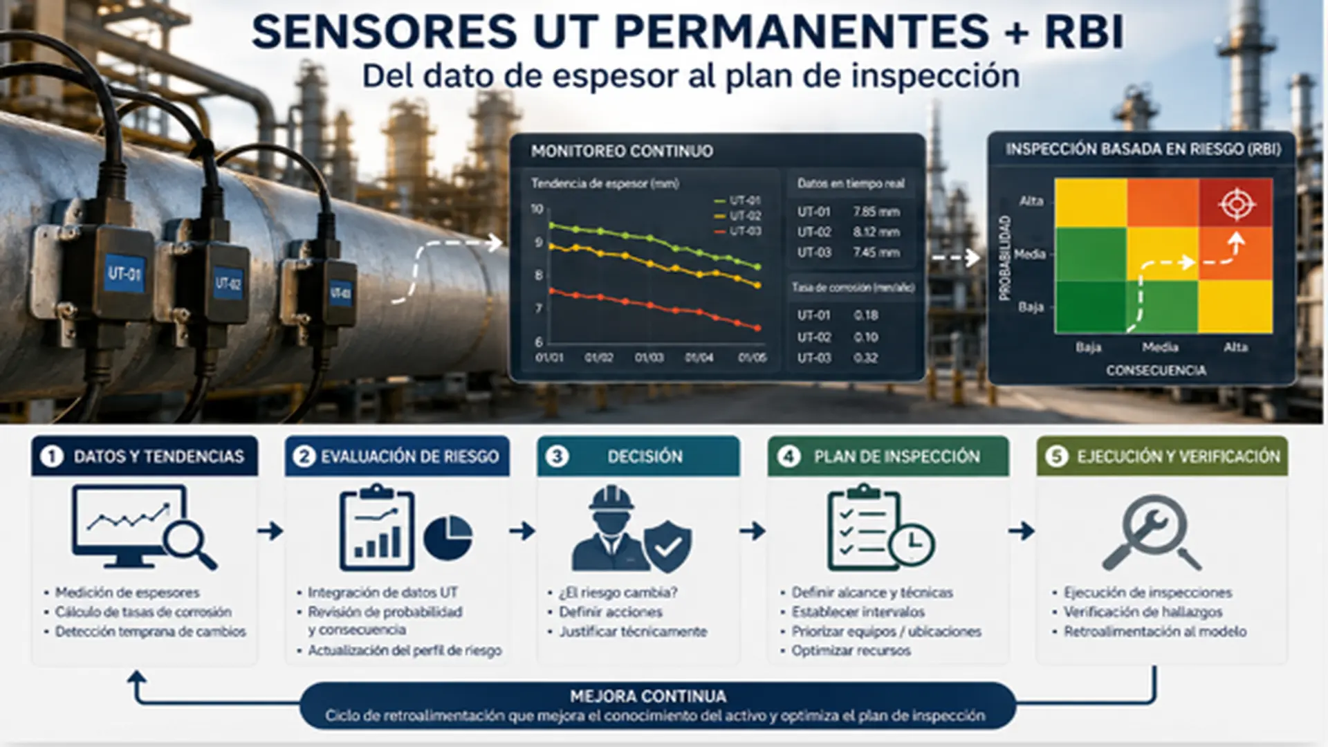
The integration of permanent UT sensors with Risk-Based Inspection changes thinning management: thickness stops being an isolated snapshot and becomes a useful trend for decision-making. Continuous corrosion monitoring improves the temporal resolution of thickness measurement, while industrial ultrasound provides technical traceability. The challenge is not to accumulate data, but to validate it, relate it to damage mechanisms, and convert it into an inspection plan that responds to the actual risk of the asset.
Permanent UT sensors for localized corrosion
Manual ultrasonic inspection offers a point reading. Permanent UT sensors remain installed in a selected location and allow time series to be obtained from practically the same physical point. That repeatability reduces part of the variability associated with repositioning, coupling, and surface preparation.
For localized corrosion, the location of the sensor is as important as its resolution. A system can measure with high precision an area that represents neither the minimum thickness nor the dominant mechanism. Therefore, selection must start from the damage history and corrosion engineering.
Prerequisites for installation:
- Chemical injections, blends, or sudden changes in composition.
- Low points, dead legs, and areas with accumulation of water or solids.
- Elbows, reducers, and sectors with potential erosion-corrosion.
- Areas where previous inspections located accelerated metal loss.
- Circuits where a process variation can modify the damage rate.
Continuous corrosion monitoring works best when it responds to a concrete hypothesis such as: what mechanism is expected, where it should manifest, and what decision would change if the rate increases. Installing sensors without that prior question produces information, but not necessarily actionable knowledge.
Permanent thickness measurement should also not be interpreted as a universal substitute for mapping. A fixed location provides high temporal resolution; a scan provides spatial coverage. Both capabilities are complementary and should be combined within the inspection plan when there is a risk of localized corrosion.
Solid hybrid strategy:
- Use coverage techniques to locate and size damage.
- Install permanent UT sensors in representative or critical positions.
- Compare the trend with process variables and expected mechanisms.
- Expand coverage when the trend indicates acceleration or anomalous behavior.
Continuous corrosion monitoring and data quality
The quantity of records does not define the quality of the program. With permanent UT sensors, a small difference in thickness can be due to real metal loss, but also to temperature, electronics, coupling, surface condition, or signal processing.
Therefore, continuous corrosion monitoring needs validation rules before calculating rates. The first question should not be: how much did the thickness change?, but rather: does the change exceed the system’s uncertainty and persist over time?
Minimum controls must cover:
- Initial calibration and periodic verification of the measurement channel.
- Temperature compensation and knowledge of its effect on acoustic velocity.
- Stability of the coupling and mechanical fixation of the transducer.
- Signal quality, signal-to-noise ratio, and criteria to discard outliers.
- Traceability of configuration, firmware, maintenance, and installation changes.
ISO 16809:2025 establishes principles for ultrasonic thickness determination using time-of-flight techniques. ASTM E797/E797M-21 constitutes another useful reference for thickness measurement by contact pulse-echo. These standards do not automatically convert a permanent system into an integrity program, but they help structure metrological and testing requirements.
The recommended workflow is simple and disciplined:
- Raw data: reading generated by the system.
- Validated data: reading that passes quality controls.
- Trend: behavior confirmed during an adequate time window.
- Interpretation: relationship with mechanism, process, and location.
- Decision: documented action within the inspection plan.
Suppose a component goes from 10.0 mm to 9.6 mm in two years. Conventional thickness measurement would allow calculating an average rate of 0.20 mm/year. That figure does not reveal whether the loss was uniform or occurred during a brief operating event.
With continuous corrosion monitoring, the time series can show when the acceleration began. If it coincides with a temperature increase, flow rate change, presence of water, or chemical modification, the integrity team gains an operational clue that a periodic evaluation would not have shown.
Permanent UT sensors thus provide valuable temporal resolution, but the mathematical slope must not be automatically accepted as the corrosion rate. It must be verified that the analyzed period is sufficient relative to the precision, repeatability, and variability of the system.
Risk-based inspection with continuous UT data
Risk-Based Inspection prioritizes resources by considering probability and consequence of failure. API RP 580 defines elements for establishing and maintaining an RBI program, while API RP 581 provides a quantitative methodology to evaluate risk and support planning.
Permanent UT sensors can enrich that process because they provide more frequent evidence on a deterioration parameter.
Continuous data should enter RBI through a decision chain:
- Validate the signal and confirm that the change is real.
- Review whether the location represents the evaluated damage mechanism.
- Compare the trend with historical data and process conditions.
- Determine whether the probability of failure or the analysis confidence changes.
- Update the inspection plan only when evidence justifies it.
Continuous corrosion monitoring does not eliminate the need for knowledge of the mechanism. An acceleration at a point near an injection point may justify additional inspection in that area, but does not necessarily allow extrapolating the new rate to an entire circuit.
A tiered response model helps avoid overreactions:
- Level 1 – Deviation: a statistical change is detected and the system is validated.
- Level 2 – Trend: metal loss is confirmed and the mechanism is reviewed.
- Level 3 – RBI Impact: it is determined whether the new evidence modifies risk, interval, or technique.
- Level 4 – Action: inspection, mitigation, repair, or engineering assessment is executed.
This approach avoids turning every industrial ultrasound oscillation into an intervention. It also avoids the opposite extreme: ignoring a relevant trend until the next calendar campaign.
DNV-RP-G101 likewise adopts a Risk-Based Inspection approach for offshore static mechanical equipment and emphasizes maintaining the program throughout the asset’s life. The idea is consistent with using continuous data: RBI must be updated when new reliable information appears, not remain frozen.
From thickness measurement to the inspection plan
The real return appears when ultrasonic thickness measurement modifies a decision. To achieve this, data must be connected to a procedure that defines responsible parties, thresholds, validation criteria, and permitted actions.
A dynamic inspection program does not mean changing dates every time a reading arrives. It means having rules to maintain, advance, or expand activities when asset behavior deviates from the assumptions used in planning.
Practical sequence structured in five steps:
- Validate the signal: review temperature, echo quality, stability, and anomalies.
- Confirm the trend: use a time window consistent with uncertainty.
- Review the mechanism: verify that the pattern matches expected damage.
- Update risk: evaluate whether evidence affects Risk-Based Inspection.
- Define action: specify technique, scope, location, date, and goal.
Permanent UT sensors also allow testing the response to a mitigation measure. If an inhibitor, temperature, or operating condition is adjusted, continuous corrosion tracking helps observe whether the subsequent trend changes consistently.
This transforms industrial ultrasound into an operational feedback tool. The question is no longer solely how much thickness remains, but expands to include at what rate it changes, under what conditions, and with what level of confidence.
The inspection program may consider:
- Expanding ultrasonic thickness measurement around the instrumented point.
- Executing UT mapping, PAUT, or another technique with greater coverage, depending on the mechanism.
- Reviewing process variables and effectiveness of mitigations.
- Recalculating remaining life or requesting a fitness-for-service evaluation when appropriate.
- Reviewing Risk-Based Inspection and circuit priority.
For mature facilities, the best scenario is a learning loop: coverage inspections find critical areas; permanent UT sensors track evolution; continuous corrosion tracking identifies changes; RBI methodology determines relevance; and the inspection program adjusts the response.
Practical UT + RBI checklist
Before integrating UT data into the RBI process, verify:
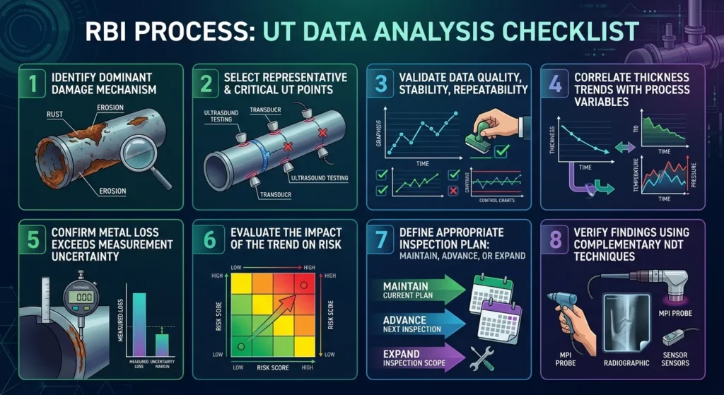
Rule of thumb: reliable data → confirmed trend → updated risk → justified action.
Conclusions
Permanent UT sensors help close the time gap between campaigns, but their value depends on location, quality, and context. Integrated with continuous corrosion tracking, reliable ultrasonic thickness measurement, and industrial ultrasound, they can provide useful evidence to the RBI methodology. The key is to establish a workflow that validates the trend, confirms the mechanism, and determines its impact before modifying the inspection program. The sensor generates readings; integrity engineering converts those readings into defensible decisions.
Referencias
- American Petroleum Institute. (2023). API Recommended Practice 580: Elements of a Risk-Based Inspection Program (4th ed.). American Petroleum Institute.
- American Petroleum Institute. (2025). API Recommended Practice 581: Risk-Based Inspection Methodology (4th ed.). American Petroleum Institute.
- ASTM International. (2021). ASTM E797/E797M-21: Standard Practice for Measuring Thickness by Manual Ultrasonic Pulse-Echo Contact Method. ASTM International.
- DNV. (2021). DNV-RP-G101: Risk based inspection of offshore topsides static mechanical equipment. DNV.
- International Organization for Standardization. (2025). ISO 16809:2025: Non-destructive testing – Ultrasonic thickness determination (3rd ed.). ISO.
FAQs on permanent UT sensors and RBI
Do UT sensors replace periodic inspection?
No. Fixed UT sensors provide temporal resolution in specific locations; coverage inspections determine the extent and distribution of damage. The inspection program should combine both capabilities depending on the mechanism and risk.
What does permanent monitoring contribute to RBI?
Continuous corrosion tracking can detect accelerations or stabilizations between campaigns. When the trend is representative and reliable, the RBI methodology can use it to review uncertainty, priorities, and intervals.
What variables can affect UT readings?
Temperature, coupling, surface condition, acoustic velocity, configuration, electronics, and geometry can affect ultrasonic thickness measurement. Therefore, every industrial UT program needs quality controls before interpreting trends.
Does a thickness alarm require advancing an inspection?
Not necessarily. Fixed UT sensors should first trigger a validation. Afterwards, the trend, mechanism, representativeness, and effect on the RBI methodology are reviewed before changing the inspection program.
Where should permanent sensors be installed?
Continuous corrosion tracking contributes most when it can reduce a specific integrity uncertainty.