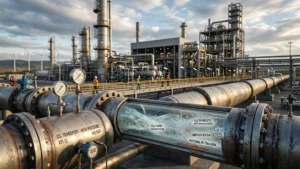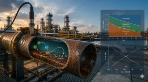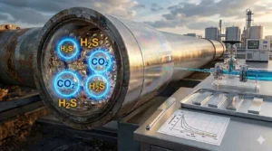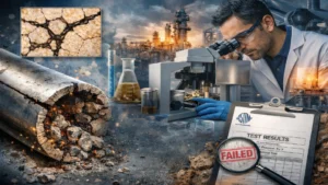
Corrosion Under Insulation (CUI) is one of the most critical, silent, and costly asset integrity management challenges within the chemical, petrochemical, and power generation industries. Although mitigation strategies have historically focused on carbon steel due to its obvious and widespread thickness loss, CUI in stainless steel exhibits completely different chemical, metallurgical, and mechanical behavior.
In these alloyed materials, the phenomenon does not manifest as large volumes of expansive rust, but rather through localized and microscopic damage mechanisms that can lead to catastrophic and sudden structural failures without prior warning.
CUI in stainless steel: Risks and chlorides
Unlike ferritic steels, stainless steels (especially austenitic series such as 304/304L and 316/316L) base their corrosion resistance on the formation of a passive chromium oxide layer that is only a few nanometers thick. The primary risk of CUI in this type of metallurgy is not wall thinning due to uniform corrosion, but rather the localized rupture of this protective film in confined, humid, and halogen-contaminated environments.
The temperature range is a significant factor in the degradation mechanisms of stainless steels:
- Temperature limit: The risk of CUI and cracking occurs starting from 50°C to 60°C.
- Critical severity range: The window of greatest danger consolidates between 60°C and 150°C.
In this thermal range, evaporated trapped water concentrates dissolved salts, creating the perfect scenario for chemical attack on the metal surface. At temperatures above 150°C, water tends to evaporate instantaneously before touching the equipment wall, which decreases the risk of CUI unless cyclic operating conditions or insulation discontinuities exist that allow local condensation.
What causes CUI in stainless steel? The lethal combination of three factors: the presence of constant moisture, high temperatures, and the primary trigger, chloride ions.
How chlorides activate CUI and SCC
The effect of chlorides on thermal insulation is the true accelerator of the problem. Water that penetrates the insulation system (whether from rain, fire protection systems, or condensation) often carries chlorides from the external environment, especially in coastal or industrial areas. Additionally, some older or low-quality insulation materials can leach chlorides directly when they become wet.
When this saline solution comes into contact with the hot surface of the steel, the water evaporates and the chlorides become concentrated. This breaks the passive chromium layer that protects the stainless steel, initiating deep pitting.
Degradation mechanisms in stainless steels
To understand the severity of CUI in these alloys, it is necessary to break down the specific degradation mechanisms that occur at the metal-insulation interface:
- Pitting Corrosion: Occurs when chloride ions break the passive layer at specific nanometer-sized points (crystalline defects, manganese sulfide inclusions, or metallurgical discontinuities). Once the layer is broken, a microscopic galvanic cell forms where the bottom of the pit acts as a very small anode and the rest of the passive surface acts as a giant cathode. This accelerates metal dissolution at the bottom, creating hidden and deep cavities.
- Crevice Corrosion: Thermal insulation in direct contact with the stainless steel surface inherently generates thousands of mechanical micro-crevices. In these areas, oxygen access is severely restricted. When the dissolved oxygen inside the crevice is depleted, the re-passivation of the material stops, while the hydrolysis of dissolved metal ions locally acidifies the medium (dropping the pH to drastically acidic levels), destroying the stability of the stainless steel within that cavity.
- Chloride-Induced Stress Corrosion Cracking (Cl-SCC): This is the final and most dangerous mechanism. It is defined as the simultaneous interaction of three factors: a susceptible material (such as austenitic steels with nickel contents between 8% and 12%), an aggressive environment (chloride concentration and temperature above 50°C), and the presence of tensile stresses (residual stresses from welding, cold forming, or thermal and operating stresses). Cracks typically originate at the bottom of a pit or crevice and propagate in a branched, transgranular manner (crossing through the metal grains), destroying the mechanical continuity of the component.
Effect of chlorides on thermal insulation
Transport mechanism of chlorides
The insulation system acts as an absorbent medium capable of retaining moisture and accumulating aggressive chemical agents via two main pathways:
- External sources (Atmospheric ingress): Rainwater, fire protection systems, process steam, or environmental condensation penetrate through poorly sealed joints, valves, or damaged protective jackets. In coastal environments or industrial complexes (near cooling towers), this water already travels loaded with dissolved chloride ions from the atmosphere.
- Internal sources (Leaching of the material itself): Certain insulating materials of older or lower specifications (such as some mineral wools or calcium silicates) intrinsically contain free chloride and fluoride impurities as a residue of their manufacturing process. When water penetrates and dampens the insulation, it interacts with the internal structure and chemically extracts these soluble halogens through leaching, transporting them toward the metal surface.
Thermal Gradient and Concentration by Evaporation
When contaminated water travels through the thickness of the insulation, it moves along a severe thermal gradient: it passes from the ambient temperature of the outer jacket to the operating temperature of the equipment on the metal surface (typically in the critical zone of 60°C to 150°C).
Upon approaching the hot steel wall, a physical separation phenomenon occurs:
- Selective evaporation: Liquid water continuously changes phase as it reaches its boiling point due to the transferred heat, escaping through the pores of the insulation as solute-free vapor.
- Deposition and insolubility: Chloride ions do not evaporate. As the solvent is lost, the remaining chloride salts precipitate and deposit directly onto the stainless steel surface.
The dynamic wet and dry cycle
Due to maintenance shutdowns, process fluctuations, or thermal weather cycles, the system experiences successive phases of wetting and drying:
- During the wetting phase: Newly entering liquid water dissolves previously deposited chlorides and drags new ions from the periphery of the insulation, accumulating them in the contact zone.
- During the drying phase: Evaporation forced by the operating temperature removes the water, leaving a crust of salts with an exponentially higher concentration.
This continuous cycle acts as a chemical accumulation mechanism that elevates the local chloride concentration from diluted traces (measured in parts per million) in the original fluid to supersaturated saline solutions at the metal-insulation interface.
Local depassivation mechanism
The result of this extreme confinement and concentration is a drastic alteration of the electrochemical microenvironment on the stainless steel surface. When the local chloride concentration exceeds the critical limit of the material at temperatures above 50°C, these halogens destroy the stability of the nanometer-thick chromium oxide film (passive layer). In the absence of free molecular oxygen under the dense insulation to regenerate this protective layer, localized pitting and crevice corrosion are irreversibly triggered, serving as initiation sites for stress corrosion cracking (SCC).
Inspection methods for CUI in stainless steel
Non-Destructive Testing (NDT) inspection oriented toward detecting CUI in stainless steel requires a diametrically opposite approach to that of carbon steel. Conventional techniques such as conventional ultrasonic thickness measurement (UT) spot checks are completely ineffective, as it is impossible to guess where a micro-crack is branching or where a millimeter-sized pit is located.
Techniques without removing insulation
How can corrosion be detected without removing the insulation?
To answer this question, advanced techniques are used to scan large areas for moisture or internal defects. The main methods for detecting CUI under insulation include:
- Real-Time / Computed Digital Radiography: Uses low-energy X-ray or gamma sources combined with digital image intensifiers to scan piping in real time. Although it does not look for thickness loss in stainless steel, it is highly effective for identifying water accumulation profiles, failures in internal supports, and hidden condensation inside the protective jacket.
- Pulsed Eddy Current (PEC): This NDT technique induces penetrating electromagnetic fields through the aluminum or stainless steel jacket of the insulation. PEC averages the remaining thickness of the component. In stainless steels (which are non-magnetic materials), its application is more complex and focuses on detecting conductive anomalies or gross volumetric variations, serving as an indicator of suspect areas.
- Neutron Moisture Gaging and Infrared Thermography: These are indirect techniques. Thermography identifies abnormal heat loss caused by water-soaked insulation. The neutron moisture gage emits fast neutrons that lose energy when colliding with hydrogen atoms in trapped water. Both techniques pinpoint “wet spots” with mathematical precision, which must then be prioritized for direct inspection.
In the following video, Eddyfi Technologies introduces the Pulsed Eddy Current Array (PECA) probe. This highly efficient solution is specifically designed for the inspection of corrosion under insulation (CUI) in insulated pipes, allowing for optimized scan times thanks to its advanced sensor array technology.
Inspection techniques involving the removal of insulation
Once condensation or suspect zones are located, the insulation is removed to specifically look for pitting and cracking (SCC) using:
- Eddy Current Array (ECA): Uses multiple electromagnetic coils activated sequentially to map the surface of the stainless steel. It is exceptionally sensitive for detecting surface and subsurface SCC cracks, even through thin layers of protective coating, measuring the length and severity of the cracking.
- Phased Array Ultrasonic Testing (PAUT) and Full Matrix Capture (FMC/TFM): Allows angular ultrasonic waves to be introduced into the material to detect the presence of transgranular SCC cracks, enabling the sizing of their depth within the equipment wall to evaluate if the asset qualifies for Fitness-for-Service criteria.
If cracking is suspected and insulation is removed in critical zones, the non-destructive techniques for detecting CUI and SCC micro-cracks shift to high-sensitivity surface methods, such as Eddy Current Array (ECA) or Phased Array Ultrasonic Testing (PAUT).
Prevention of chloride cracking and SCC
Successful mitigation of CUI and SCC in stainless steels cannot rely exclusively on inspection; it must be integrated from the design and material selection phase. Engineering strategies are divided into stress control, chemical barriers, and insulation medium control:
1. Chloride Cracking (Environmental control)
- Strict insulation specification: Use only water-repellent insulation materials (which actively repel water) that rigorously comply with the ASTM C795 standard. This standard guarantees that the material has leachable chloride and fluoride levels so low that they sit safely within the chemical acceptance curve for stainless steels.
- Use of corrosion inhibitors: Implement insulation that incorporates factory-applied sodium silicate-based inhibitors. These silicates leach along with the chlorides and compete for active sites on the stainless steel surface, forming a temporary protective glassy film that neutralizes the halogen attack.
2. Stress corrosion cracking (Stresses and coatings)
- High-integrity coating systems: The modern golden rule of the NACE SP0198 standard dictates that all stainless steel operating in the critical range of 50°C to 150°C must be coated before installing insulation. High-temperature cure phenolic epoxy coatings or Thermal Spray Aluminum (TSA) coatings are specified. These act as an absolute physical barrier; if water with chlorides penetrates the insulation, it hits the paint and never comes into contact with the susceptible metal surface.
- Residual stress relief: Since SCC requires tensile stresses, reducing residual stresses through appropriate post-weld heat treatment (PWHT) or via peening techniques to induce surface compressive stresses drastically decreases susceptibility to chloride cracking.
- Aluminum foil barriers: In some applications, the stainless steel pipe is wrapped with a thin layer of pure aluminum foil before the insulation is placed. The aluminum acts as a galvanic sacrificial anode, cathodically protecting the stainless steel and absorbing the attack of incident chlorides.
Conclusions
The phenomenon of Corrosion Under Insulation (CUI) in austenitic stainless steels differs radically from carbon steel. Instead of uniform and visible thickness loss, damage manifests through localized mechanisms such as pitting and crevice corrosion, which serve as initiation sites for chloride-induced stress corrosion cracking (Cl-SCC), causing sudden and catastrophic structural failures.
The operating thermal gradient is the main kinetic driver of the problem. While the activation limit for Cl-SCC is situated between 50°C and 60°C, the critical window of maximum severity consolidates between 60°C and 150°C, a range where wet and dry cycles generate supersaturated saline solutions at the metal-insulation interface.
Effective mitigation of CUI and SCC cannot depend exclusively on inspection plans. It requires a multifactorial control strategy from the design phase that combines the use of high-integrity barrier coatings (under the NACE SP0198 standard), the selection of water-repellent insulation with low leachable halogen content (per ASTM C795), and the reduction of mechanical tensile stresses.
Conventional ultrasonic spot thickness inspection is obsolete for mapping this phenomenon in stainless steels. Integrity management demands the application of innovative strategies using techniques that do not require insulation removal (such as Open-Flow Digital Radiography or thermography) to locate moisture retention, followed by advanced surface and volumetric characterization methods (such as Eddy Current Array – ECA and PAUT) to size SCC micro-cracks.
References
- AMPP. (2020). Standard Practice: Control of Corrosion Under Insulation and Fireproofing Materials, A Systems Approach (NACE SP0198-2020). Association for Materials Protection and Performance.
- API. (2020). Damage Mechanisms Affecting Fixed Equipment in the Refining Industry (API RP 571, 3rd ed.). American Petroleum Institute.
- ASTM International. (2023). Standard Specification for Wicking Type Thermal Insulation for Use Over Austenitic Stainless Steel (ASTM C795-23).
- Winnik, S. (Ed.). (2015). Corrosion Under Insulation (CUI) Guidelines (2nd ed.). European Federation of Corrosion (EFC) Woodhead Publishing.
Frequently Asked Questions (FAQs)
What causes SCC in insulated systems?
Stress Corrosion Cracking (SCC) in insulated systems is caused by the simultaneous action of three factors: a susceptible alloy (such as austenitic stainless steel), the presence of mechanical tensile stresses (either operational or residual from welding), and a corrosive environment concentrated in chlorides at optimal temperatures for the reaction (above 50°C).
How to detect corrosion without removing insulation?
To detect corrosion or the conditions that cause it without removing the insulation, advanced NDT techniques are used, such as Open-Flow Digital Radiography (to see internal profiles and the presence of water), Pulsed Eddy Current (PEC) for wall screening, and tools like Infrared Thermography and Neutron Moisture Gaging to precisely locate water retention zones within the insulation.
What causes CUI in stainless steel?
CUI in stainless steel is caused by the ingress of water (from rain or condensation) into the thermal insulation system. The water dissolves or leaches chlorides from the environment or from the insulation itself and, upon coming into contact with the steel surface in the critical temperature range (60°C to 150°C), continuously evaporates, concentrating the chlorides until it breaks the passive layer of the metal and activates localized attacks.
How do chlorides influence SCC?
Chlorides act as highly aggressive depassivating agents. They penetrate and locally destroy the protective chromium oxide film of the stainless steel, generating pits. The bottom of these pits concentrates the mechanical stresses of the equipment; under this state of stress, the tip of the pit fractures microscopically, initiating the rapid and branched growth of SCC cracks. Add Image
What methods detect CUI under insulation?
The main indirect and direct detection methods under insulation include Neutron Moisture Gaging and Thermography (to find moisture), and Real-Time Radiography (RTR). For the fine detection of SCC cracks once insulation is removed at suspect points, the most effective methods are Eddy Current Array (ECA) and Phased Array Ultrasonic Testing (PAUT).
How to prevent SCC in insulated equipment?
Prevention of SCC is achieved by interrupting any of the components of the damage triangle: applying protective barrier coatings (per NACE SP0198) to prevent chlorides from touching the metal, employing low-leaching, low-chloride water-repellent insulation materials (compliant with ASTM C795), and implementing heat treatments or surface compression to reduce tensile stresses in welds.