Table of Contents
Thermal monitoring in industrial furnaces helps maintain operational reliability, improve energy efficiency, and protect personnel. Hot spot detection makes it possible to identify failures at early stages and prevent damage to refractories, coils, burners, and metallic structures. This article describes the technologies used, the critical components that must be monitored, and the detailed operation of the inspection process. In addition, it integrates recent advances that have transformed infrared thermography and predictive maintenance in industry.
What are hot spots and how do they form?
Hot spots are localized areas where the temperature significantly exceeds the normal expected value for a furnace surface or component. In industrial furnaces, these hot spots may represent early structural failures or thermal insulation losses that put process stability and the mechanical integrity of the equipment at risk.
Formation mechanisms
- Refractory degradation: Erosion, thermal cracking, spalling, or natural aging of the refractory facilitates heat escape toward the external shell, causing dangerous temperature increases.
- Leaks at joints and inspection doors: Defective seals, deteriorated gaskets, or improperly installed covers allow heat to escape to the exterior.
- Thermal overload in coils and process tubes: In hydrocarbon-fired heaters, coils operate at severe temperatures. A hot spot on a tube may indicate internal coking, blockages, or wall thickness loss.
- Alterations in the combustion pattern: A poorly adjusted burner may direct excessive flame toward a localized area, causing overheating.
- Failures in insulation systems: Loss of coatings, corrosion in thermal blankets, or moisture in insulation materials increases thermal conductivity, generating abnormal heating.
How to detect hot spots in industrial equipment?
Hot spot detection in thermal equipment relies on the application of infrared thermography tools and continuous monitoring systems. For stationary equipment, such as heat treatment furnaces or process heaters, combinations of portable instruments and fixed systems are used depending on criticality and operating conditions.
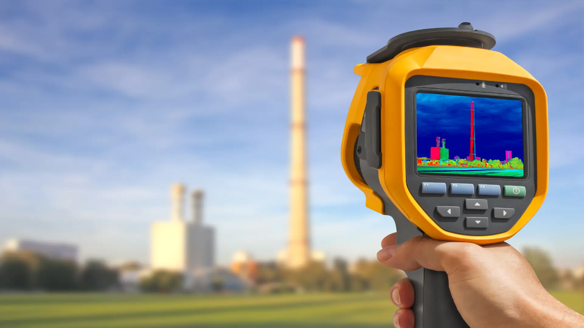
Portable thermographic inspection
Portable thermal cameras are ideal for scheduled inspections. Their mobility allows inspection of external furnace areas, joints, inspection doors, exposed piping, and hard-to-reach zones. They are used by certified thermography technicians to identify anomalies in thermal maps. Their application enables obtaining a complete thermal map of the furnace, identifying overtemperature zones.
Recommendations for use:
Perform periodic inspections during operation.
Adjust material emissivity according to surface type.
Record historical data to evaluate trends.
Fixed thermal monitoring systems
These systems operate 24/7 and enable continuous monitoring in industrial furnaces that require high reliability. They typically integrate:
- Industrial thermocouples strategically placed in critical zones.
- Industrial IR cameras in reinforced enclosures.
- Thermal analysis software systems.
- PLC/SCADA integration.
- Automatic alarms at critical thresholds.
These systems are installed at strategic points: side walls, roofs, areas near burners, coils, and ducts.
Thermal sensors and process pyrometers
In high-temperature internal zones, optical pyrometers based on specific wavelengths are used to obtain accurate readings without direct contact.
Real time infrared thermography
The development of high-resolution cameras has made it possible to obtain real-time thermal images, improving analysis and prediction capabilities.
Smart systems with advanced analytics
Today, part of thermal detection in furnaces includes artificial intelligence, automatic trend comparisons, and predictive alarms.
Predictive analysis and predictive maintenance
Thermal monitoring combined with analysis software makes it possible to anticipate failures, generate alarms for hot spot detection, and schedule predictive maintenance. This reduces unplanned shutdowns and increases industrial energy efficiency.
Technology in industrial thermal monitoring
In recent years, technological developments in thermal monitoring have evolved toward fully integrated solutions that combine specialized hardware, advanced algorithms, and industrial connectivity. Industrial thermal cameras have expanded their sensitivity range, accuracy, and durability, while software has incorporated tools for data correlation, trending, diagnostics, and automated reporting.
These advances allow applied infrared thermography to be a key tool today for process thermal safety and industrial energy efficiency. Some specialized companies have developed platforms that integrate continuous monitoring, smart alarms, and AI-based analysis. Among them, providers such as Viper Imaging, along with other industry integrators, have driven advanced solutions that facilitate real-time thermal analysis as well as automated data interpretation to strengthen predictive maintenance.
Furnace temperature monitoring
Thermal monitoring systems are divided into two categories: fixed equipment and portable equipment, each designed for specific objectives within industrial furnaces.
Fixed equipment for continuous monitoring
These include:
Continuous operation industrial thermal cameras
Continuous-operation industrial thermal cameras are designed for permanent installation in furnaces and high-temperature equipment, typically mounted in industrial enclosures with forced ventilation or water-cooling systems that ensure thermal stability and operational reliability.
These solutions enable real-time monitoring of critical areas such as furnace side walls, roof and dome, burner zones, combustion chambers, process coils, feed tubes, internal stacks, and hot gas ducts. By providing continuous thermal images, these systems facilitate early detection of hot spots, insulation losses, refractory degradation, and thermal misalignments that may compromise equipment integrity and energy efficiency.
Industrial software based systems
Software-based thermal monitoring systems complement infrared camera hardware through advanced analysis platforms. These solutions enable continuous thermal image capture, generation of historical trends by monitored zone, and configuration of automatic alarms in response to predefined temperature deviations.
They also facilitate data export to predictive maintenance systems, asset management platforms, or reliability analysis tools. Specialized providers such as Viper Imaging have developed integrated ecosystems that combine infrared cameras, advanced thermal analysis, SCADA system integration, and smart alarms, strengthening operational decision-making and the prevention of critical failures.
Portable equipment
Portable thermal inspection equipment is a key tool for spot evaluations, thermal audits, and condition-based maintenance programs. Their main advantage lies in operational flexibility, allowing technical personnel to assess multiple assets and zones without the need for fixed installations, especially in areas with limited access or during scheduled shutdowns.
Handheld thermal cameras
Handheld thermal cameras are primarily used for periodic inspections and localized diagnostics. They are used to assess the condition of external refractories, joints, doors, and seals, as well as accessible coil tubes and exposed metallic structures. They also allow inspection of areas near burners, where high thermal gradients can accelerate deterioration mechanisms. These inspections provide valuable information to identify incipient thermal anomalies, validate operating conditions, and prioritize corrective maintenance actions.
Portable infrared thermometers
Portable infrared thermometers are intended for rapid, spot surface temperature measurements. Although they do not generate thermal images, their speed of use makes them practical tools for operational checks, temperature comparisons between similar components, and confirmation of specific thermal conditions. Their application is common in field inspection routines, operational support tasks, and preliminary validation of potential thermal deviations detected by other methods.
Furnace components that must be monitored
Industrial furnaces have multiple critical zones subject to thermal degradation. Monitoring should include:
- Internal refractory: Identify cracking, spalling, or erosion.
- External metallic structure: An increase in shell temperature may indicate refractory failure.
- Burners and combustion zones: Thermal imbalance, flame deviation, or incomplete combustion can be detected.
- Doors, accesses, and seals: Common points of thermal leakage.
- Coils and process tubes.
Thermal Monitoring in Furnaces
A structured procedure should be followed that includes:
- The internal refractory must be evaluated to identify the presence of cracks, spalling, erosion, or thickness loss, as these deterioration mechanisms directly affect thermal insulation capability and may lead to localized overheating or progressive structural damage.
- The external metallic structure of the equipment constitutes an indirect indicator of the condition of the internal refractory. An abnormal increase in shell temperature is usually associated with refractory lining failures, insulation loss, or zones with advanced degradation that allow excessive heat transfer to the exterior.
- In burners and combustion zones, thermal analysis makes it possible to detect temperature imbalances, deviations in flame pattern, or incomplete combustion conditions. These anomalies are usually related to air–fuel mixing problems, obstructions, component wear, or operational misalignments that impact process efficiency and safety.
- Doors, accesses, and seals represent critical points from a thermal standpoint, as they are frequent zones of heat leakage. Detection of elevated temperatures or irregular gradients in these areas indicates deficient sealing, mechanical deformation, or material deterioration, with a direct impact on energy consumption and operational stability.
- Finally, coils and process tubes must be monitored to identify abnormal thermal variations that may be associated with internal fouling, blockages, metallurgical degradation, or inadequate flow conditions. These thermal deviations are often precursors to overheating failures, loss of thermal efficiency, or accelerated mechanical damage.
Trends in industrial thermal Mmnitoring
The future of thermal monitoring and hot spot detection in industrial furnaces points toward digitalization:
- IoT and connected systems: Smart sensors sending real-time data to the cloud.
- Applied artificial intelligence: Algorithms for failure prediction and temperature optimization.
- Remote monitoring: Furnace supervision from centralized platforms without physical presence.
- Integration with energy efficiency: Automatic adjustment of combustion and heat distribution to optimize energy consumption.
These trends allow industrial furnaces not only to operate safely but also with maximum efficiency.
Conclusion
Thermal monitoring in industrial furnaces is a fundamental tool for hot spot detection, operational control, and predictive maintenance. The integration of advanced technologies such as infrared thermography and smart systems has increased analytical and preventive capabilities. By monitoring critical components such as refractories, coils, burners, and metallic structures, industrial plants can maximize efficiency, safety, and equipment service life.
References
- API. (2020). API Recommended Practice 573: Inspection of Fired Boilers and Heaters. American Petroleum Institute.
- ISO 18434-1:2008. Condition Monitoring and Diagnostics of Machines — Thermography — Part 1: General procedures. Available on the International Organization for Standardization (ISO) website.
- ISO. (2012). ISO 18434-1: Condition Monitoring and Diagnostics of Machines – Thermography – Part 1: General Procedures. International Organization for Standardization.
- Viper Imaging. (2023). Thermal Monitoring Solutions for Industrial Furnaces and Process Equipment. Viper Imaging Technical Reports.
- Article: Flame monitoring and anomaly detection in steel reheating furnaces (J. Vanhaeverbeke et al., 2025) on thermal monitoring using thermal cameras and automated analysis.