Table of Contents
The quality of welding is an overriding factor of very special attention for the structural integrity of any industrial project. Defects such as undercut welds, porosity, and surface cracks can compromise joint strength and lead to premature failure.
This article discusses the main surface defects in welding, their causes, consequences and how weld inspection processes can help prevent them effectively.
What are weld defects?
Weld defects are irregularities that compromise the integrity, strength, or aesthetics of a metal joint. They are classified into internal defects and surface defects, the latter being easier to detect and evaluate using weld inspection techniques such as visual examination or non-destructive testing.
Although superficial, these weld defects can be a reflection of deeper problems, such as poor technique, contaminated materials or inadequate parameters. Therefore, their analysis is significant to ensure joint reliability.
Common errors that cause surface defects
Detecting the origin of welding defects allows corrective actions to be taken. Among the most common causes are:
- Incorrect welding parameters (amperage, voltage, speed), which induce weld undercut or excess reinforcement.
- Surfaces contaminated with rust, moisture or grease, which generate weld porosity.
- Poor welder’s technique, which favors irregular beads and cracks in welding.
- Wet or incompatible electrodes that compromise the quality of the process.
- Adverse environmental conditions, responsible for welding porosity or surface cracks.
- Poor cleaning between passes, common origin of inclusions and superficial welding defects.
Main surface defects in welding
The following is a description of the most common welding defects found on the surface of welded joints:
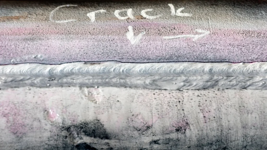
1.cracks in welds: small visible fractures in the surface of the seam that can be:
- Longitudinal (along the axis of the bead)
- Transverse (perpendicular to the bead)
- Marginal or crater (at the end of the weld)
- Hot cracks: They are formed when the molten metal cools.
- Cold cracks: They appear after solidification, due to residual stresses or presence of hydrogen.
Welding cracks are highly dangerous, since they tend to propagate, compromising the structure. Their detection should be a priority during weld inspection.
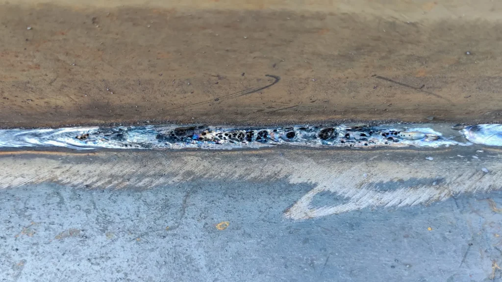
2. Weld porosity: The formation of gaseous cavities on the surface, generated by gases trapped during solidification. It can occur as
- Isolated porosity.
- Grouped or agglomerated porosity.
- Micro surface porosity.
Weld porosity decreases the density of the material and is a potential source of cracks.
3. Surface inclusions: Visible residues such as trapped slag or non-metallic particles that solidify on the surface of the weld. They are usually associated with poor cleaning technique between passes or improper use of flux.
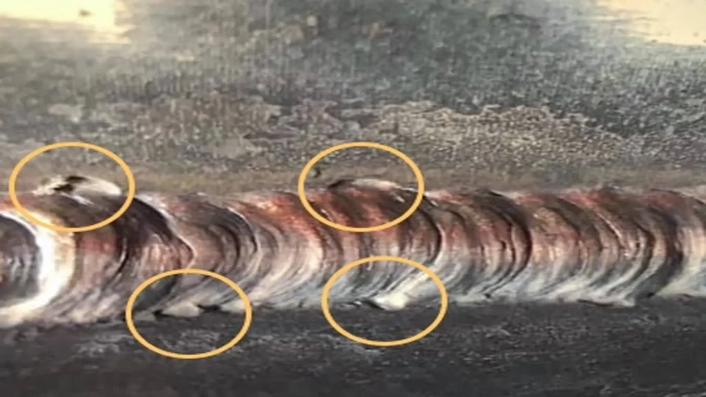
4. Undercut weld: Grooves along the bead edge caused by excessive heat or poor electrode handling. This defect reduces the fatigue strength of the weld.
This welding defect consists of a groove along the seam edge. It occurs due to excessive heat or poor electrode handling. The undercut weld weakens the fatigue strength and can be easily detected by visual weld inspection.
- Over-reinforcement: When the bead protrudes too far above the base surface. Although visually it may appear solid, it generates undesirable stress concentrations.
- Irregular bead profile: An unstable bead shape, excessive waviness or misalignment is evidence of technique, speed, or amperage problems. Although not a critical weld defect, a bead with too much material generates undesirable stresses, affecting structural homogeneity.
- Lack of filler: Presence of visible depressions or grooves between passes, especially in multipass welds. This is due to insufficient weld metal supply.
- Surface contamination: Visible stains, oxides, oil or metallic particles that alter the adhesion of the seam and can cause other welding defects such as cracks or porosity.
- Weld spatter: Small droplets of metal expelled from the arc that adhere to the surface. Although they do not always affect strength, they impair the surface finish and require additional cleaning.
- Poorly finished craters: These are depressions at the end of the seam, caused by abrupt interruptions of the arc without adequate filler that generate depressions that favor weld cracks, especially in stress zones.
- Surface misalignment: Bad joint between adjacent beads or between the edges of the joint. It is common in manual processes with poor electrode guidance or incorrect joint adjustment.
To reduce the occurrence of these welding defects, good practices should be implemented from the beginning of the welding process. Among the most effective actions are:
- Properly train welders in appropriate techniques and quality criteria.
- Strictly control welding parameters such as voltage, current, feed rate and electrode type.
- Apply visual welding inspection protocols and non-destructive testing according to material and structure standards.
Table with the characteristics of surface defects in welding
| Surface defect | Technical description | Common causes | Impact on quality |
|---|---|---|---|
| Welding cracks | Visible longitudinal, transverse or crater fractures. | Rapid cooling, residual stresses or poor parameter selection. | Compromise structural strength and integrity. |
| Welding porosity | Cavities generated by trapped gas. | Moisture, contamination, draft in the welding arc. | They decrease density and can propagate cracks. |
| Surface inclusions | Slag or non-metallic particles trapped on the surface. | Poor cleaning between passes, poor flux. | They affect the continuity and resistance of the cord. |
| Undercut welding | Groove along the edge of the weld bead. | Excessive amperage, poor technique. | Decreases resistance to fatigue and cyclic loading. |
| Over-reinforcement | Cord protrudes excessively above the surface. | Low feed rate, excess input. | Generates concentrations of effort. |
| Irregular bead profile | Wavy, unstable or poorly formed cord. | Inadequate technique, irregular oscillation. | Poor appearance, possible weakening of the cord. |
| Lack of filler | Visible depressions between passes. | Insufficient material supply, poor coverage. | Reduction of the effective weld thickness. |
| Surface contamination | Presence of oxides, oils or residues. | Poor cleaning, inadequate preparation. | Generates other defects and affects adhesion. |
| Spatter | Metal droplets ejected from the arc and adhered to the surface. | Excess amperage, incorrect polarity. | Deterioration of the finish and need for rework. |
| Poorly finished craters | Depression at the end of the cord due to inadequate interruption. | Abrupt cutting of the arch without filling the crater. | Area prone to cracks and fissures. |
| Surface misalignment | Misalignment between cords or poorly positioned edges. | Poor gasket preparation, incorrect guidance. | It weakens the bond and affects the flow of forces. |
Inspection methods to detect surface defects
Proper weld inspection can detect these defects before the joint enters service. The most common methods used to identify surface discontinuities are as follows
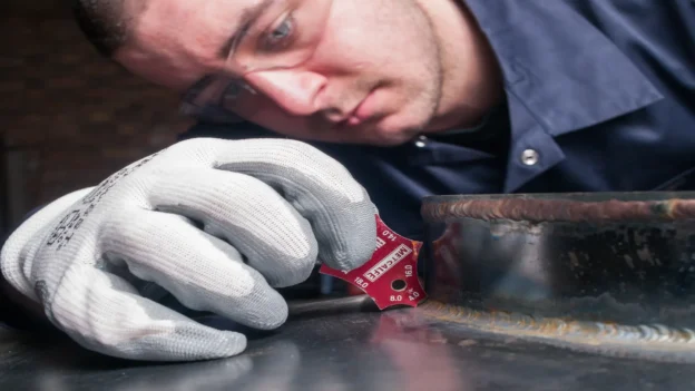
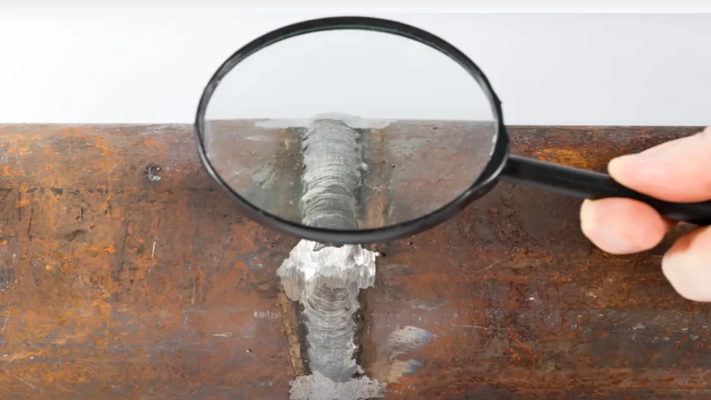
- Visual inspection (VT): This is the most basic and widely used method. A qualified inspector can identify defects such as undercutting, visible cracks and porosity using magnifying glasses, LED lights or high resolution cameras.
- Liquid penetrant test (PT): Ideal for detecting discontinuities open to the surface. It uses a liquid with high capillarity, followed by a developer, to make any defects visible under visible or ultraviolet light.
- Magnetic particle testing (MT): Applied to ferromagnetic materials, to identify cracks in surface and sub-surface welds by attracting magnetic particles in areas with field disturbance.
- Eddy currents (ET): Uses electromagnetic fields to recognize variations in the conductivity of the material. Effective for detecting porosity in welds or cracks in conductive materials.
- Ultrasonic surface inspection (UT): Ultrasonic technology is used to detect changes in the propagation of waves reflected by discontinuities. Methods, such as angle beam, allow weld inspection and high precision surface analysis.
- Acoustic Emission (AET): Allows real-time flaw detection during load testing. Although it is most commonly used for internal defects, it is also useful for certain cracks in welds that are active at the surface.
- Infrared thermography: It is used to detect weld defects through surface temperature variations caused by differences in thermal conductivity due to pores or cracks.
- Laser methods: Techniques such as laser interferometry or 3D scanning detect topographical irregularities with high accuracy. They are ideal for automated inspections of critical welds.
- Automated and robotic inspection systems: Robotics enable repetitive visual and multi-protocol inspections, even in complex conditions or hazardous environments.
Importance of weld inspection
Proper weld inspection not only improves quality, but also prevents weld defects from going undetected. Identifying conditions such as weld cracks, weld porosity or undercut welds early avoids structural failures, rework costs and operational risks.
These defects, although they may appear minor to the naked eye, can seriously compromise weld quality if not identified and corrected in a timely manner through visual methods and non-destructive techniques.
Standard regulating permissible weld defects
ISO 5817 and AWS D1.1 are references to evaluate the quality of welds according to defined acceptance levels.
Conclusions
Surface defects such as undercut welds, weld porosity and weld cracks directly affect the strength and durability of welded joints. Their timely detection through proper weld inspection ensures safety and regulatory compliance in industrial projects. In addition, it is essential that welders are properly trained and that the correct welding parameters are used to minimize the occurrence of defects. The quality of a weld depends not only on the equipment and materials used, but also on the skill and knowledge of the welder.
References
- AWS D1.1 Structural Welding Code – Steel, American Welding Society
- ISO 5817:2014 – Fusion-welded joints in steel, nickel, titanium and their alloys — Quality levels for imperfections
- API 1104 – Welding of Pipelines and Related Facilities
- Handbook of Visual Inspection Techniques – ASNT
Frequently asked questions about surface defects in welding
What is the most critical surface defect in a weld?
Surface cracks are considered the most dangerous. These discontinuities can propagate rapidly, compromising structural integrity and leading to catastrophic failure if not detected in time.
How does the heat-affected zone (HAZ) affect surface defects?
Micro-cracks can be generated in the HAZ due to thermal or metallurgical stresses. These are especially sensitive in materials with high hardness or inadequate heat treatments.
Can surface defects always be repaired?
In many cases yes, but in the case of deep or localized cracks in critical areas, complete removal of the seam and a new qualified welding procedure may be required.
What is the relationship between parameter control and weld quality?
Poor control can lead to lack of penetration, lack of weld fusion or cracking. Adjusting current, voltage and speed is vital to avoid defects and achieve reliable weld quality.