
At the core of countless industrial operations, the types of compressors play a vital role in increasing the pressure of gases for a wide variety of processes. From gas transport to power generation and process automation, they represent not only a technical necessity, but also a strategic component in achieving energy efficiency, productivity and operational reliability.
By definition, compressors are designed to compress a gaseous substance. To predict compressor performance and calculate the loads of the various components, we need methods to predict the properties of the gas. Process compressors are used to compress a wide range of gases under various conditions.
Thermodynamic fundamentals of compressor design
Thermodynamic properties
To predict compressor performance, methods are needed to calculate the enthalpy, internal energy and entropy of the gas. It is also often convenient to use the volume isentropic exponent nV and the temperature isentropic exponent nT.
Thermodynamic laws
To calculate the cycles of a compressor, the energy equation, the relationships that apply to an isentropic change of state and the law of fluid flow through a restriction are required.
The energy equation for a fixed mass of gas simply states that the energy gain of the gas is equal to the work done on the gas minus the heat transferred from the gas to the surroundings.
For compressor conditions, we can ignore changes in potential and chemical energy. In applications where the energy equation is used for a fixed mass of gas, we can generally also ignore changes in kinetic energy.
Compression cycles
Every compressor is based on a thermodynamic principle: increasing the pressure of a gas involves doing mechanical work on it. This process, ideally isentropic, involves transformations in the enthalpy, temperature, specific volume and density of the gas. The actual efficiency of the process depends on multiple factors: input conditions, heat dissipated, equipment design and types of compressors used1.
The work supplied to a compressor is intended to increase the pressure of the gas, its temperature and any heat transferred out of the compressor. In most cases, the requirement is to increase the gas pressure using as little energy as possible.
If the compression process is adiabatic, i.e., there is no heat transfer between the compressor and the outside, the least work will be done if the process is isentropic. This implies that there are no losses in the compressor, which is an unattainable goal, but can be used as a basis for compression efficiency2.
The isentropic efficiency of a compressor is defined as the work required to compress the gas in an isentropic process divided by the actual work used to compress the gas. The efficiency of a compressor is usually expressed as isentropic efficiency.
Key parameters include:
- Compression ratio (Outlet pressure / Inlet pressure).
- Isentropic efficiency (ratio between ideal and real work).
- Specific power (kW/100 SCFM).
- Mass flow and volumetric ratio.
General classification of industrial compressors
According to the British Compressed Air Society (2001, as cited in Mobley, 2001), compressed air systems should be designed with consideration of leakage losses, volumetric efficiency and demand control3. Industrial compressor types are broadly classified as dynamic and positive displacement:
Dynamic compressors
Dynamic compressors are rotary equipment operating at a constant pressure, where the rapidly rotating element accelerates the air as it passes through the element, converting the velocity load into pressure. Partly in the rotating element and partially in stationary diffusers or blades4. They can be subdivided into centrifugal or axial.
They transfer energy to the gas by accelerating particles and subsequently converting velocity into pressure, they work by accelerating gas molecules through a rotor or impeller, subsequently converting that kinetic energy into pressure through a diffuser. The performance of a dynamic compressor is affected by external conditions, for example, a change in inlet temperature causes a change in capacity. They can be subdivided into centrifugal or axial.
Centrifugal dynamic compressors
They feature a radial flow design, in which air is drawn in axially and expelled by centrifugal force. They are designed to handle large volumes of gas at low pressures, transferring energy to the fluid through high-speed rotating impellers. These are ideal for continuous processes and are present in refineries, cryogenic plants and large Heating, Ventilation and Air Conditioning (HVAC) plants. In the following figure 1, a picture of this type of compressor is appreciated.

Description and operation of a centrifugal compressor
They consist of the following components: Outer casing (A) containing a part of the stator, called a diaphragm bundle (B), and of a rotor consisting of a shaft (C), one or more impellers (D), a balance drum (E) and a thrust collar (F). The central shaft, the impellers arranged in series, the diffusers, and the supporting casings. Figure 1, shows a detailed cross-section of a multistage centrifugal compressor, where the main components of the system mentioned above are clearly observed.

The rotor is driven by a hub (G) and held in position axially by a thrust bearing (I), while rotating on plain bearings (H). The rotor is equipped with labyrinth seals (L) and, if necessary, oil film seals at the ends (M).
The gas is introduced into the compressor through a suction nozzle and enters an annular chamber (inlet volute), flowing from this to the center from all directions in a uniform radial pattern. On the opposite side of the chamber to the suction nozzle is a flap to prevent gas vortices.
Description and operation of an axial dynamic compressor
They operate with multiple stages of fixed blades where the air flow moves continuously and in an axial direction, i.e. parallel to the axis of rotation, so they have an elongated and compact geometry. They consist of a series of stages formed by rotating discs (rotors) and stationary discs (stators), arranged alternately. Due to their high rotational speed, they are perfectly suited to gas turbines for electricity generation and aircraft propulsion.
Figure 3, shows a MAN axial compressor working in combination with a radial stage, where the pressure is increased to higher values.

Positive displacement compressors: operation and industrial application
Unlike dynamic compressors operate at constant flow, compressing the gas trapping finite volumes and reducing them mechanically, in a closed chamber. It works by compressing a certain amount of gas, confining it in a space of decreasing volume, and forcing it out once the desired pressure is reached. This type of compression is cyclic, precise and highly efficient at low and medium pressures, which makes them key pieces in various industries.
The compression cycle in a positive displacement compressor follows three basic stages:
- Intake: Gas enters a chamber or cavity at atmospheric pressure through an inlet valve.
- Compression: A moving element – such as a piston, screw, vanes or lobes – progressively reduces the volume available to the gas, which increases its pressure.
- Discharge: Once the target pressure is reached, an outlet valve is opened and the compressed gas is expelled into the process line.
Types of positive displacement compressors
- Reciprocating (reciprocating) compressors: use a piston inside a cylinder.
- Screw compressors: with intermeshing helical rotors.
- Rotary vane compressors: with an eccentric rotor and moving vanes.
- Lobe or scroll compressors: less common, but effective in certain specialized applications.
Each type is described below:
- Reciprocating (reciprocating) compressors: Reciprocating compressors work by the linear movement of a piston inside a cylinder, generating compression by reducing the volume of the chamber where the gas is confined. During the downward stroke, the piston allows the gas to enter, and in the upward stroke compresses it, forcing it out through a discharge valve. These compressors can be single or multi-stage, depending on the pressure required, and are available in lubricated or oil-free versions. They are especially suited for high-pressure applications and handling complex industrial gases, such as ammonia, hydrogen or CO₂, making them common in chemical plants, CNG stations, and industrial compressed air systems.
- Screw compressors: Screw compressors employ two intermeshing helical rotors – male and female – to trap the gas and progressively reduce its volume as it moves along the axis of the rotors. Sealing between the lobes can be achieved by oil injection, water injection or with precise mechanical tolerances (in oil-free models). This technology allows continuous operation, without valves or pulsations, resulting in a stable, efficient and low-noise gas flow. They are widely used in refrigeration systems, HVAC, petrochemical processes and other applications requiring constant flow rates at medium pressures.
- Rotary vane compressors: This type of compressor has a rotor mounted eccentrically inside a cylinder, which is inserted sliding vanes that move radially outward by centrifugal force. As the rotor rotates, the vanes form chambers of variable volume that suck in, compress and discharge the gas. Their design is compact, with few moving parts, and provides relatively uniform flow, although with lower efficiency than screw compressors. They are ideal for low to medium pressure applications, such as pneumatic tools, vacuum systems, light refrigeration and auxiliary industrial machinery.
- Scroll compressors (or spirals): Scroll compressors use two spirals: one fixed and one moving, which move in an eccentric orbit without rotating, generating a series of cavities that decrease in size toward the center as the gas moves forward. This progressive reduction in volume compresses the gas quietly, efficiently and vibration-free. Because of their oil-free design and smooth operation, scrolls are particularly suitable for air conditioning systems, medical refrigeration, laboratories, and sensitive electronic applications. Although they are not common in heavy industrial processes, their efficiency and low maintenance make them increasingly popular in high-precision HVAC systems
Industrial applications
Positive displacement compressors are widely used in:
- Chemical and petrochemical plants, where precise compression of reactive or combustible gases is required.
- HVAC and refrigeration systems, due to their ability to operate at constant pressures and maintain stable flow rates.
- Food and pharmaceutical industry, especially oil-free models.
- Industrial automation and pneumatics, in the supply of compressed air for tools and actuators.
In the following video you will learn in a visual and didactic way the principle of operation of positive displacement compressors, a fundamental technology in the compression of industrial gases. Courtesy of: THORS e-learning solutions
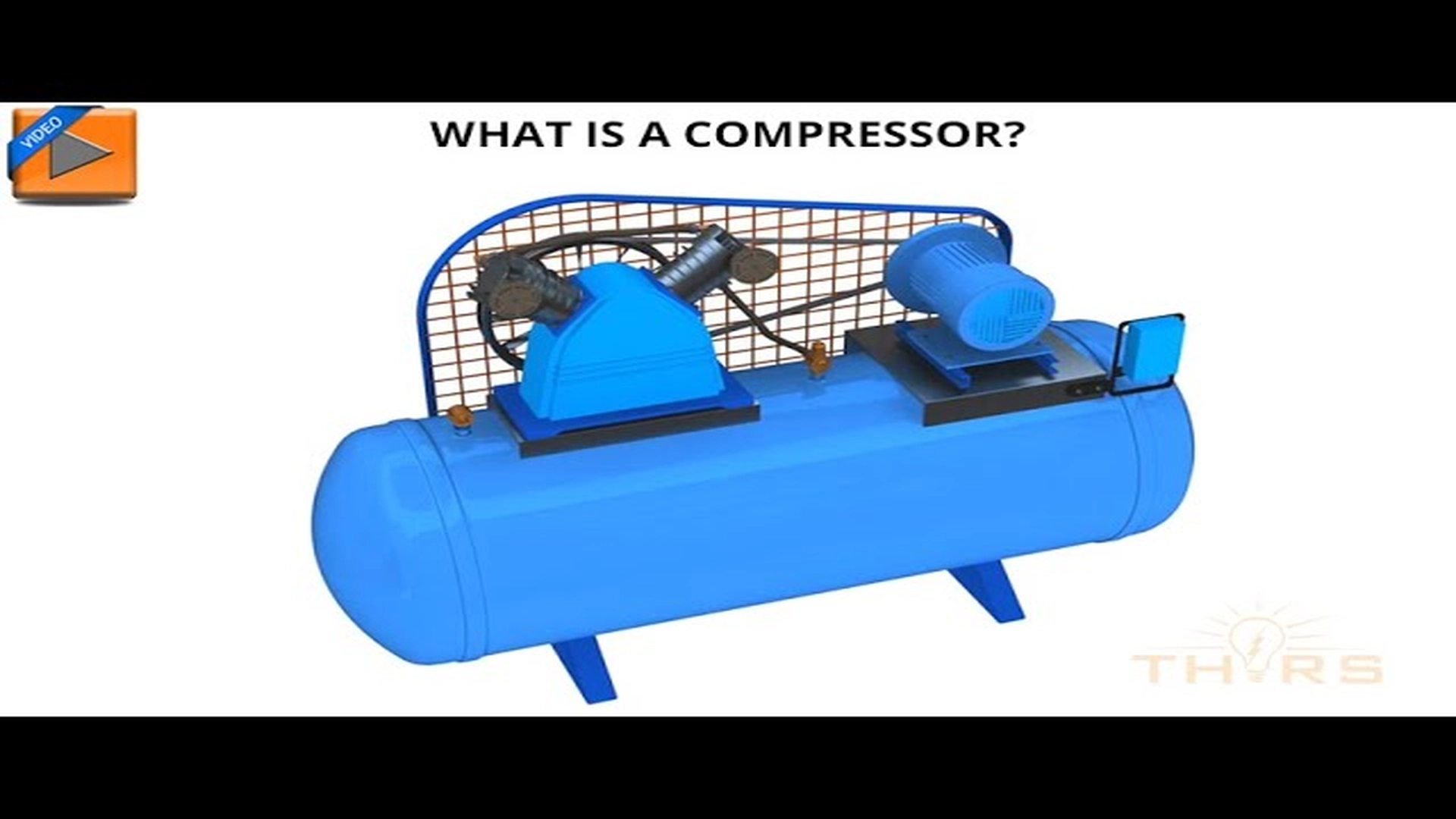
How a positive displacement compressor works.
Energy efficiency
Energy consumption in compressors can represent between 8% and 15% of the total electricity of an industrial plant. Therefore, the selection should consider not only instantaneous efficiency, but also long-term performance.
Key strategies:
- Use of variable frequency drives.
- Intercooling in multi-stage systems.
- Heat recovery for fluid preheating or heating.
- Leakage reduction in compressed air networks.
- Operating point optimization.
- Aerodynamic comparison: Centrifugal vs. axial.
comparison: centrifugal vs. axial
| Aspect | Centrifugal compressor | Axial compressor |
| Flow direction | Radial | Axial |
| Energy transfer | Impeller and diffuser | Rotor y estator por etapas |
| Compression ratio | High per stage (~3:1 to 10:1) | Low per stage (~1.2:1) |
| Specific flow | Low to medium | High (ideal for high flow rates) |
| Compact design | Yes (1 stage may be sufficient) | No (requires many stages) |
| Typical applications | Industrial plants, HVAC, turbochargers | Gas turbines, aviation, combined-cycle plants |
Each industry imposes specific pressure, flow, reliability and regulatory requirements:
- Workshops: small piston or screw compressors.
- Refineries: multistage centrifugal or alternative high pressure.
- Chemical plants: screw or centrifugal compressors for corrosive gases.
- Industrial HVAC: scroll, screw and centrifugal.
- Food industry: oil-free screw.
Factors such as ease of maintenance, operational reliability, spare parts availability, energy efficiency and regulatory compliance (API 618/672/619 as appropriate) also play a role.
Advanced maintenance and reliability
The maintenance of modern compressor types goes beyond the replacement of filters and lubricants. The current trend is towards condition-based monitoring (CBM) and predictive maintenance.
Techniques and tools:
- Vibration and ultrasound analysis.
- Temperature and pressure monitoring.
- Piezoelectric sensors and SCADA systems.
- Non-destructive inspections (NDT) in chambers and seals.
- Dynamic balancing of rotating components.
Conclusions
Choosing the ideal compressor cannot be based on initial price alone. A technical approach that considers the operating principles, the type of compressor, its energy efficiency and its adaptability to the specific application is essential to achieve high levels of industrial performance and sustainability.
Compressors are a special category of process machines. They operate with compressible fluids and are characterized by an appreciable increase in fluid density between the first and last compression stage.
The compression process is often distributed in several stages, a term used to indicate an elementary system composed of moving vanes, in which the fluid acquires energy, and fixed vanes, in which the energy is transformed.
References
- Edmister, Wayne C., Applied Hydrocarbon Thermodynamics, Gulf Publishing, 1961, L. of C. 61-17939.
- Gas Properties and Compressor Data, Ingersoll-Rand Company Form 3519D.
- Mobley, R. K. (Ed.). (2001). Plant engineer’s handbook (pp. 587, 589–599). British Compressed Air Society. https://doi.org/10.1016/B978-075067328-0/50037-9
- Compressors—Handbooks, manuals, etc. I. Hanlon, Paul C.