Table of Contents
- How do centrifugal gas compressors work?
- Fundamental principles of operation
- Thermodynamic analysis of the process
- Impeller design characteristics
- Midstream application requirements
- Pressure management in gas pipelines
- Performance optimization strategies
- Protection systems in centrifugal compressors.
- Inlet condition management
- Future technology trends
- Conclusions
- References
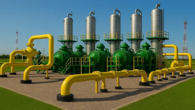
Centrifugal compressors are the backbone of modern midstream gas transportation operations, offering unmatched efficiency in transporting natural gas through continental pipeline networks.
These dynamic machines achieve pressure ratios of up to 4:1 per stage while maintaining operational availability above 98%, making them indispensable for the continuous flow of gas in transmission systems.
This comprehensive analysis examines the technical advantages, operational parameters, and performance optimization strategies that position centrifugal compressors as the preferred technology for midstream applications.
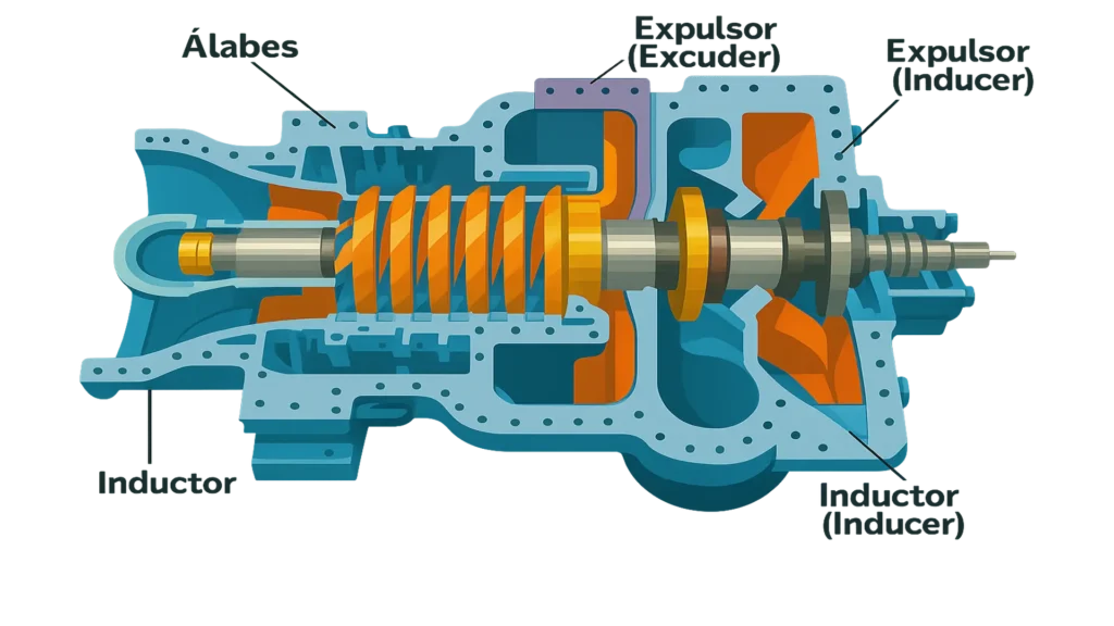
How do centrifugal gas compressors work?
Centrifugal compressors raise gas pressure by adding kinetic energy (speed) to the gas as it flows through an impeller. Kinetic energy increases potential energy (static pressure) by slowing the flow through a diffuser. The pressure increase in the impeller (in most cases) is equal to the increase in the diffuser.
As the flow passes through the centrifugal impeller, it forces it to spin faster as it moves away from the axis of rotation. The energy applied to the gas flow is proportional to the local rotational speed of the flow multiplied by the local tangential speed of the impeller.
The flow leaving the centrifugal impeller travels at an accelerated speed until it passes through a stationary compressor, causing it to decelerate and transform energy. The reduction in speed causes an increase in pressure.
Fundamental principles of operation
Advanced thermodynamic analysis reveals a polytropic compression efficiency of 78-85% in modern pipeline applications, with impeller tip speeds reaching 450-550 m/s to achieve an optimal pressure ratio. Dynamic compression principles use modifications of the Euler equation to maximize energy transfer through controlled diffusion processes.
Critical optimization of the specific speed between 500 and 800 (US units) ensures stable operation with variable molecular weight compositions.
Thermodynamic analysis of the process
Centrifugal compressors operate on the principle of dynamic compression, where the kinetic energy imparted by the rotating impeller is converted into pressure energy by controlled deceleration in the diffuser system.
The compression process follows a polytropic trajectory with an efficiency typically ranging from 78% to 85% for piping applications.
The fundamental energy equation governing centrifugal compression is:
Height (H) = U₂²/gc – U₁²/gc + (C₂² – C₁²) /2gc + (W₁² – W₂²) /2gc
Where:
- U = tip speed of the blade
- C = absolute speed
- W = relative speed
- gc = gravitational constant
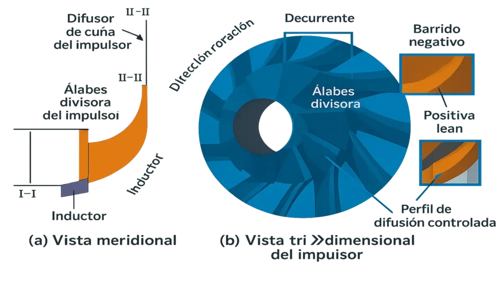
Impeller design characteristics
Modern centrifugal compressors use backward-curved impellers with specific speeds ranging from 500 to 800 (US units), optimized for high efficiency and stable operation.
The impeller discharge angle typically ranges from 15 to 45 degrees, balancing pressure increase with efficiency requirements.
Key design parameters:
- Inlet ratio between hub and tip: 0.3-0.5
- Impeller outlet width: 5-15% of impeller diameter
- Blade discharge angle: 15-45 degrees
- Specific speed: 500-800 (US units)
Midstream application requirements
Compressor stations operate at compression ratios of 1.2 to 2.0 per stage, with suction pressures of 600 to 1200 psig, requiring continuous service capability exceeding 8760 hours per year. Flow capacity specifications require a throughput of 50-500 MMSCFD per unit, maintaining pressure differentials in transmission segments of 80-320 kilometers.
Operational availability targets exceed 98%, with reduction capacities reaching 60-100% of nominal flow to accommodate fluctuations in demand.
Pressure management in gas pipelines
Gas pipelines experience continuous pressure drops due to friction losses, requiring strategic compression to maintain adequate supply pressure. Typical compressor stations operate at:
- Suction pressure: 600-1,200 psig
- Discharge pressure: 800-1,450 psig
- Compression ratio: 1.2-2.0 per stage
- Flow rates: 50-500 MMSCFD per unit
Operating duty cycle
Midstream centrifugal compressors must maintain continuous operation with minimal downtime. Industry standards require:
- Availability: >98% annually
- Maintenance intervals: 8,000-25,000 hours
- Service life: 25-30 years
- Reduction capacity: 60-100% of nominal flow rate
Performance optimization strategies
Three-dimensional optimization using CFD achieves efficiency improvements of 2 to 5% by designing the meridional flow path and controlling tip clearance with tolerances of 0.5 to 1.0 mm.
The implementation of a variable frequency drive enables efficiency improvements of 5 to 15% at partial load, with reduction ratios reaching 50% of the rated speed, while maintaining the overpressure margin requirements.
The advanced impeller profile with backward curved blade angles of 15 to 45 degrees optimizes the pressure rise coefficient and minimizes secondary flow losses.
Aerodynamic efficiency improvement
Modern compressor designs incorporate advanced optimization using computational fluid dynamics (CFD) to maximize isentropic efficiency. Key improvement techniques include:
Impeller optimization:
- Three-dimensional blade profiling
- Meridional flow path optimization
- Minimization of tip clearance (0.5-1.0 mm)
- Surface finish optimization (Ra < 1.6 μm)
Diffuser design:
- Paddle diffusers for high pressure ratio applications.
- Optimization of the volute for uniform pressure distribution.
- Advanced materials for thermal expansion control.
Variable speed operation
Variable frequency drives (VFDs) enable precise flow control and efficiency optimization in response to varying pipeline demands. Speed control provides:
- Reduction ratio: Up to 50% of rated speed
- Increased efficiency: 5-15% improvement at partial load
- Reduction of choke losses: Elimination of losses in inlet guide vanes
- Energy savings: Proportional to the speed-cube ratio.
Protection systems in centrifugal compressors.
Modern overpressure control systems maintain a minimum overpressure margin of 10-15% using predictive algorithms and fast-acting recirculation valves with response times of less than 1 second. Overpressure detection uses real-time flow coefficient monitoring and pressure rise characteristic mapping to prevent flow reversal conditions.
Advanced control logic integrates upstream and downstream coordination to optimize overpressure protection throughout the system and minimize recirculation energy losses.
Problems: The phenomenon of surge and overpressure
These problems in a compressor are not the same, although both are transient phenomena and potentially destructive if not controlled.
1. Surge in compressors
- It occurs in centrifugal or axial compressors when the gas flow rate falls below a critical limit.
- It is an unstable aerodynamic phenomenon: the pressure at the discharge is so high that the gas flows in the opposite direction, towards the suction, generating violent oscillations in the flow.
- It is characterized by:
- Intense vibrations.
- Knocking and noise.
- Risk of damage to impellers, bearings, and seals.
- Drop in system efficiency.
- It is represented on the compressor performance map as an area to the left of the surge curve (low flow, high pressure).
2. Overpressure
- This is a hydraulic or pressure phenomenon in pipes and equipment, more common in liquid lines (although it can occur with gases).
- Caused by:
- Sudden shutdown of pumps or valves that close too quickly.
- Water hammer.
- Incorrect sizing of control valves or process lines.
- Consequences:
- Damage to pipes, gaskets, flanges.
- Safety valve failures.
- Risk of structural failure.
Although both manifest as violent pressure or flow events, surge is an internal, aerodynamic phenomenon of the compressor, while overpressure is an external, hydraulic phenomenon of the system. Both require different mitigation strategies (anti-surge valves vs. relief/water hammer valves).
Control system design
1. Modern anti-overpressure systems incorporate
- Fast-acting recirculation valves: Response time <1 second.
- Predictive overpressure control: Algorithms that prevent approaching the overpressure line.
- Multiple levels of protection: Warning, alarm, and trip functions.
- Integration with process control: Coordination with upstream/downstream equipment.
2. Rotor dynamics
Critical speed analysis ensures safe operation across the entire speed range. Key considerations:
- First critical speed: 120-150% of maximum continuous speed.
- Bearing selection: Babbitt-type tilting pad bearings for high-speed applications.
- Shaft materials: High-strength alloy steels (AISI 4140/4340).
- Balancing standards: API 617 Grade 2.5 or higher.
Comprehensive monitoring systems track more than 200 process parameters, including vibration spectra up to 10 kHz, bearing temperature profiles, and real-time performance curve mapping.
Advanced sensor networks integrate accelerometers, RTDs, and pressure transmitters with 0.1% accuracy for the development of predictive maintenance algorithms.
Integration with SCADA enables unmanned operation with millisecond data acquisition speeds and hierarchical alarm management in distributed control architectures.
3. Efficiency Optimization Techniques
Optimizing the inlet condition reduces compression work by 2% to 4% by controlling temperature and minimizing pressure loss with properly designed inlet ducts.
Scale mitigation strategies prevent annual efficiency degradation of 3% to 8% through high-efficiency filtration systems and anti-scaling coatings for impellers.
Inlet condition management
Optimal inlet conditions maximize compressor efficiency:
- Temperature control: Inlet cooling reduces compression work.
- Pressure optimization: Minimizes upstream losses.
- Flow distribution: Uniform velocity profiles.
- Moisture removal: Prevents efficiency degradation.
Future technology trends
Digital twin technology enables real-time performance optimization through physics-based modeling with computational fluids, dynamic integration, and machine learning algorithms.
The development of advanced materials focuses on ceramic matrix composites to increase temperature capacity to 200 °C and on nano-coatings to improve fouling resistance by 15% to 20%.
The implementation of artificial intelligence facilitates predictive control algorithms with 99.5% accuracy in fault prediction and autonomous optimization of operating parameters.
1. Digital transformation
Advanced technologies that improve compressor performance:
- Digital twins: Virtual modeling for optimization
- Artificial intelligence: Predictive analysis and control
- IoT integration: Enhanced sensor networks
- Blockchain: Secure exchange of data and maintenance records
2. Advanced materials
Emerging materials for better performance:
- Ceramic matrix composites: Higher temperature capability
- Nano-coatings: Improved surface properties
- Smart materials: Adaptive response to operating conditions
- Advanced alloys: Improved strength-to-weight ratio
Conclusions
Centrifugal compressors remain the optimal choice for midstream gas transportation, offering superior reliability, efficiency, and operational flexibility. Their ability to handle large volumes continuously with minimal maintenance makes them indispensable for modern pipeline operations.
The key to maximizing centrifugal compressor performance lies in understanding the complex interaction between aerodynamic design, mechanical systems, and operating parameters.
By implementing comprehensive monitoring, predictive maintenance, and performance optimization strategies, operators can achieve efficiency levels exceeding 85% while maintaining the high availability requirements essential for midstream operations.
References
- https://www.fs-elliott.com/how-does-a-centrifugal-compressor-work
- https://www.sundyne.com/the-basics-centrifugal-gas-compressors
- https://www.araner.com/blog/what-is-a-centrifugal-compressor-and-how-does-it-work
- https://www.solarturbines.com/en_US/solutions/oil-and-gas/gas-transmission.html