Magnetic particle inspection is a non-destructive testing method based on the principles of electromagnetism, specifically on the phenomenon of magnetic flux leakage. When a ferromagnetic material is subjected to an external magnetic field and contains discontinuities that intersect or are close to the surface, distortions occur in the magnetic flux lines. These distortions generate localized leakage fields that attract finely divided ferromagnetic particles, thereby revealing the presence, location, and approximate orientation of the discontinuities.
The magnetic particle inspection method stands out for its ability to detect fine cracks, inclusions, laps, seams, and other planar or volumetric discontinuities that compromise the structural integrity of critical components. Its application ranges from in-process inspection during manufacturing to in-service evaluations of components subjected to cyclic loading.
Fundamentals of magnetism in materials
Ferromagnetic materials are characterized by a high relative magnetic permeability, typically between 100 and 100,000, which concentrates the magnetic flux lines within the material.
When the applied field encounters a discontinuity, especially one perpendicular to the flux lines, a redistribution of the field occurs, giving rise to three key effects: the flux lines concentrate in areas of higher permeability, avoiding the discontinuity; a fraction of the flux emerges and re-enters the surface, generating a surface leakage field.
The edges of the discontinuity act as local magnetic poles that attract and retain ferromagnetic particles. The interaction between these poles and the particles is the basis of the visible indication interpreted by the inspector.
Variables affecting leakage field intensity
The intensity and detectability of the leakage field depend mainly on the orientation, size, and depth of the discontinuity, the intensity of the applied field, and the geometry of the part. Maximum sensitivity is achieved when the discontinuity is approximately perpendicular to the magnetic field, whereas defects parallel to the field may not generate detectable leakage.
Surface discontinuities produce stronger leakage fields and, under optimal conditions, the method is effective to a depth on the order of 6 to 8 mm; beyond this range, sensitivity decreases rapidly.
The field intensity must be sufficient to achieve local saturation of the material without generating excessive residual magnetization or non-relevant indications. Additionally, changes in section, sharp corners, or holes may produce geometric flux concentrations that result in false indications.
Applicable materials: Ferromagnetism criterion
The applicability of the magnetic particle technique is strictly limited to materials exhibiting ferromagnetic behavior, which is an essential condition for the viability of the method. This restriction implies that the inspector’s first decision is to confirm the magnetic nature of the material and its ability to be magnetized.
Suitable materials include carbon steels and low-alloy steels used in structures, piping, construction components, and forged parts, which represent the most common application.
Martensitic stainless steels of the 400 series (such as 410, 416, 420, and 440) are also compatible, although with somewhat reduced sensitivity due to their lower permeability. Cast iron and ductile iron are likewise inspectable, although the presence of graphite may generate background indications that complicate interpretation. Certain nickel–iron alloys that retain ferromagnetic properties complete the group of materials typically inspectable by this method.
Magnetization Techniques
The selection of the magnetization technique is critical to ensure that relevant discontinuities are subjected to an adequate magnetic field in terms of direction and magnitude. The inspector must consider part geometry, expected defect orientation, accessibility, field conditions, as well as productivity and portability requirements.
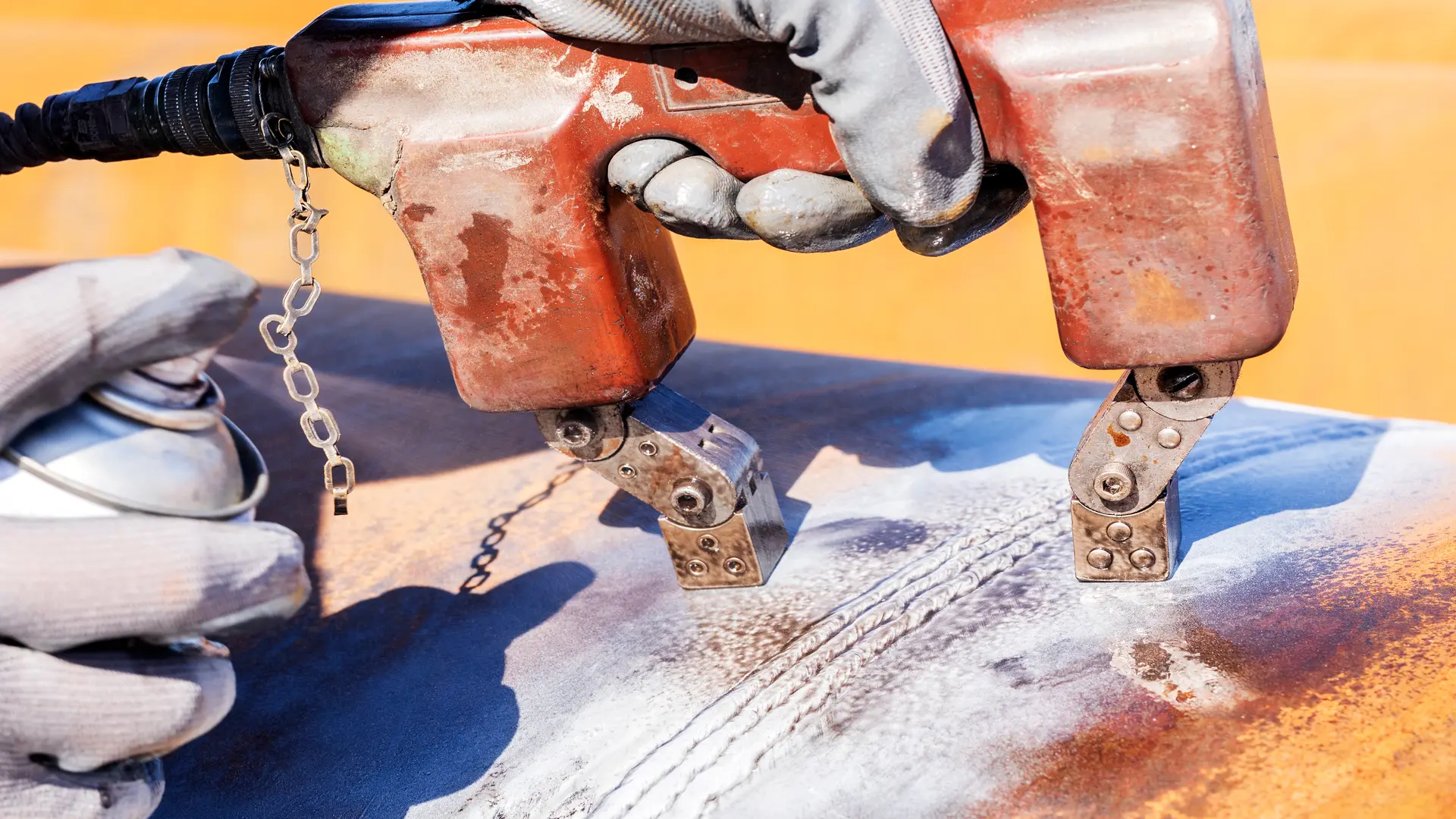
Electromagnetic yoke Mmagnetization
The electromagnetic yoke is a portable U-shaped device that generates a longitudinal magnetic field between its poles when energized on the surface of the part. It is widely used in the inspection of welded structures and large components in the field, as it offers versatility, portability, and does not require electrical contact with the material. Its main limitation is that the effective field is restricted to the distance between the poles, usually between 75 and 200 mm, which necessitates multiple placements and orientations to achieve complete coverage.
Circular magnetization by direct current flow
In this technique, a high-intensity current, on the order of 500 to 6000 A, is passed through the part, generating a circular magnetic field around the conductor in accordance with Ampère’s law. It is particularly suitable for shafts, bars, and cylindrical parts, as well as for the inspection of through-holes, offering high sensitivity to longitudinal discontinuities and relatively uniform fields in symmetric geometries. However, it requires reliable electrical contact, with the risk of arc burns and the potential for local overheating if parameters are not properly controlled.
Coil magnetization (Induction)
Coil magnetization is based on placing the part inside or near an energized coil, generating a longitudinal field along the axis of the coil. It is used for short cylindrical parts, rings, bearings, and high-production automated applications, allowing rapid inspections without direct contact with the part and facilitating integration into automated lines. Its effective field is limited by the size and design of the coil and generally offers less portability compared to manual solutions.
Multidirectional magnetization
Since discontinuities may have unknown or variable orientations, standard practice requires inspections using at least two mutually perpendicular field directions, typically 0° and 90°. Modern equipment allows fields to be applied sequentially or simultaneously using multidirectional techniques, increasing the probability of detecting defects unfavorably oriented for a single magnetization.
Applications of the Magnetic Particle technique
Magnetic particle inspection (MT) is a non-destructive testing technique widely used for the detection of surface and near-surface discontinuities in ferromagnetic materials. Its versatility, rapid execution, and high sensitivity make it a fundamental tool at multiple stages of the industrial component life cycle.
During manufacturing, the MT technique is used for quality control of forged, cast, machined, and welded parts. It is commonly applied to the inspection of weld beads, heat-affected zones (HAZ), shafts, gears, bolts, valves, and structural components, enabling the identification of solidification cracks, cooling-induced cracks, inclusions, and manufacturing defects before components enter service. At this stage, early detection of discontinuities helps reduce rework, rejections, and premature failures.
In maintenance processes and in-service evaluations, magnetic particle inspection is essential for identifying cumulative damage associated with mechanisms such as fatigue, mechanical overloads, vibrations, and residual stresses. Components subjected to cyclic loading—such as rotating shafts, railway wheels, lifting hooks, cranes, pressure vessels, and steel structures—are frequently evaluated using MT to detect incipient cracks before they evolve into critical failures.
The technique also has significant applications in specific industrial sectors. In the oil and petrochemical industry, it is used to inspect flanges, bolts, bolted connections, pump and valve components, as well as welded areas in pressure equipment. In the energy sector, including thermal, hydroelectric, and wind power generation, it is applied in the evaluation of rotors, shafts, turbine components, and support structures. In the aerospace and railway industries, MT is a standard technique for inspecting critical components where structural integrity is paramount.
In the field of metallurgy and heat treatment, magnetic particle inspection is used to detect cracks induced by processes such as quenching, tempering, welding, or cold straightening. These defects, often invisible to the naked eye, can severely compromise the mechanical strength of the component if not detected in a timely manner.
The technique is also used in integrity audits, failure analysis, and quality assurance, providing clear visual evidence of discontinuities that facilitates technical decision-making, component acceptance or rejection, and documentation in accordance with international codes and standards.
It is important to emphasize that the effective application of magnetic particle inspection requires proper selection of the magnetization method, appropriate orientation of the magnetic field, control of operational variables, and qualified personnel. When applied within its range of validity, the MT technique provides reliable, repeatable, and high technical value results, consolidating its position as one of the most efficient tools for preventing failures in ferromagnetic components.
Conclusions
Magnetic particle inspection is a highly reliable and efficient NDT technique for the detection of surface and near-surface discontinuities, provided it is applied within its technical scope. Its rapid execution, portability, and favorable cost–benefit ratio make it a key tool in industrial quality control programs.
The effectiveness of MT testing depends directly on strict compliance with its technical requirements, including confirmation of the ferromagnetic nature of the material, proper selection and qualification of procedures in accordance with applicable standards, the use of properly calibrated equipment, and the involvement of competent and certified personnel.
The true value of magnetic particle inspection lies in a thorough understanding of its fundamentals and limitations, enabling professionals to judiciously assess when it is the most appropriate method and when alternative techniques should be employed, thereby ensuring technically defensible results and effective failure prevention.
References
- American Society for Nondestructive Testing. (2016). Magnetic particle testing (3rd ed.). ASNT Press.
- American Society for Nondestructive Testing. (2020). Nondestructive testing handbook, Vol. 7: Magnetic particle testing (3rd ed.). ASNT Press.
- ASTM International. (2023). ASTM E1444/E1444M-23: Standard practice for magnetic particle testing. ASTM International.
- ASTM International. (2022). ASTM E709-22: Standard guide for magnetic particle testing. ASTM International.
- Blitz, J. (1997). Electrical and magnetic methods of non-destructive testing. Springer.