
Table of Contents
- Concept and scope of field machining and flange facing
- Why does it impact mechanical integrity?
- When should in-situ machining be applied?
- Applications of field machining in industrial assets
- Parallelism and runout correction
- Failures requiring field machining
- ASME B16.5 and technical acceptance criteria
- Acceptance criteria for field machining according to ASME
- How to correct flange alignment in situ
- In line boring in critical assets
- Technology applied to portable machining
- Operational safety during plant shutdown
- Industry and training in field machining
- Conclusions
- Frequently Asked Questions (FAQs)
Field machining is a critical practice for restoring the geometric and sealing conditions of flanges in process systems without dismantling equipment or transporting it to a workshop. In many industrial facilities, loss of flatness or flange misalignment can lead to leaks, compromise system integrity, and increase downtime.
In-situ alignment and flange facing allow these deviations to be corrected under criteria such as ASME B16.5, ensuring surfaces suitable for reliable sealing. Understanding geometric tolerances and surface roughness parameters is essential to ensure mechanical integrity in critical industrial assets.
Concept and scope of field machining and flange facing
What is field machining?
Field machining consists of performing machining processes directly on installed assets without dismantling them or transporting them to a workshop. For this purpose, high-precision portable equipment capable of operating on pipelines, valves, pressure vessels, and heat exchangers is used.
Unlike conventional machining, the work is carried out under real operating conditions or during scheduled shutdowns. This reduces downtime and avoids structural disassembly in critical systems.
In facilities regulated by codes such as ASME B31.3 or ASME Section VIII, field machining makes it possible to restore sealing surfaces while maintaining dimensional control and technical traceability.
In industrial practice, these types of interventions are typically performed during scheduled maintenance windows, where machining speed and precision directly influence plant shutdown duration.
What is flange facing and grinding?
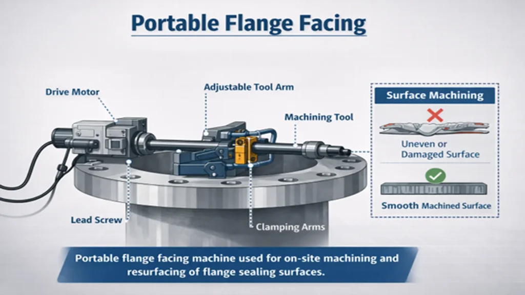
Flange facing is the process of machining the sealing face to restore flatness and surface finish. Although flange grinding may be used in specific situations, machining provides greater control over the profile and the phonographic pattern.
ASME B16.5 establishes that RF and FF faces must present a concentric or spiral serrated finish. The recommended roughness ranges between 125 and 250 µin (≈3.2–6.3 µm Ra), depending on the gasket type.
Field machining makes it possible to restore these conditions when damage occurs due to corrosion, erosion, or over-torque.
Why does it impact mechanical integrity?
Mechanical integrity depends on the system’s ability to contain pressure without leakage. A surface that is out of flatness generates uneven load distribution on bolts, affecting the gasket seating stress defined in ASME PCC-1.
Axial or radial runout deviations induce additional stresses in the flanged joint. In large diameters, even small eccentricities can amplify stresses.
Field machining corrects these deviations and restores geometric conditions compatible with the original equipment design.
When should in-situ machining be applied?
In-situ machining should be considered when the following are detected:
- Recurrent leaks in flanged joints
- Localized corrosion on the sealing face
- Angular or axial misalignment
- Accumulated thermal deformation
During a scheduled shutdown, field machining allows intervention without replacing complete components, provided that the minimum thickness meets the requirements of the applicable code.
Applications of field machining in industrial assets
Field machining is applied to assets where geometric precision is critical for pressure containment and structural stability.
After performing field machining operations, such as flange facing or housing boring, it is essential to verify repair quality using inspection techniques. In this context, Non-Destructive Testing in industrial inspection allows the integrity of the component to be evaluated without affecting its operation.
Flanges in process piping
In systems regulated by ASME B31.1 or B31.3, standard flanges follow the dimensions of ASME B16.5 up to NPS 24” and ASME B16.47 for larger diameters.
Continuous exposure to pressure, temperature, and vibration may lead to progressive loss of flatness or damage to the sealing face.
Field machining makes it possible to restore RF, FF, or RTJ surfaces without dismantling entire pipe sections.
In large-diameter systems or critical process lines, avoiding pipe disassembly represents a significant advantage in terms of safety and intervention time.
Flange alignment in industrial valves
Valves regulated by ASME B16.34 and API standards may present misalignment after maintenance or internal component replacement.
Through field machining and in-line boring, parallelism and concentricity can be corrected, ensuring geometric compatibility with the original design.
Pressure vessel flanges
In vessels designed under ASME Section VIII, flanges may be integral or standard flanges welded to nozzles.
Field machining allows restoration of the sealing surface as long as the minimum required thickness is maintained and the design configuration is not altered.
Heat exchanger flanges
Shell-and-tube exchangers are designed under ASME Section VIII and TEMA criteria.
After prolonged thermal cycles or multiple openings for cleaning, thermal distortion and loss of parallelism may occur.
Field machining corrects these conditions directly on site.
Parallelism and runout correction
Parallelism and axial or radial runout are critical parameters in any flanged joint.
Assembly of flanged Joints ASME PCC-1
ASME PCC-1 (Guidelines for Pressure Boundary Bolted Flange Joint Assembly) is a standard that establishes best practices for the correct assembly of flanged joints in pressure equipment and piping systems. Its objective is to guarantee sealing integrity and prevent leaks through standardized procedures for surface preparation, gasket selection, bolt lubrication, torque application, and controlled tightening sequences.
Field machining techniques allow machining operations to reference the actual axis of the component, ensuring concentricity and dimensional stability.
Table 1. presents the regulatory framework that contextualizes field machining within the ASME code system and industrial standards.
Table 1. Applicable standards according to asset type
| Asset | Main design code | Complementary standards |
|---|---|---|
| Process piping | ASME B31.3 | ASME B16.5 / B16.47 |
| Power piping | ASME B31.1 | ASME B16.5 |
| Pressure vessels | ASME Section VIII | ASME PCC-2 |
| Shell & tube exchangers | ASME Section VIII | TEMA |
| Flanged joint assembly | ASME PCC-1 | — |
The correct identification of the applicable regulatory framework is essential before performing any on-site machining intervention.
Failures requiring field machining
Flanged joints are subjected to internal pressure, thermal cycles, and mechanical loads. When these conditions generate geometric deviations, field machining restores conditions compatible with the design.
Damaged sealing surfaces, corrosion, or deformation of components are some of the causes of failures in flanged pipe joints that may require on-site machining operations.
Loss of flatness: It may originate from corrosion, mechanical damage, or thermal deformation. A non-flat surface prevents uniform gasket compression. Field machining corrects the surface within acceptable tolerances.
Axial and angular misalignment: It may result from induced stresses or improper installation. This generates uneven bolt loading and increases leak risk.
Roughness out of specification: Surface finish influences gasket behavior. Values outside specification may cause extrusion or gasket failure.
ASME B16.5 and technical acceptance criteria
Most practices used in industrial maintenance and equipment repair are based on international standards developed by organizations such as ASME engineering standards for pressure equipment.
The dimensions and characteristics of these connections are defined in standards such as ASME B16.5 Pipe Flanges and Flanged Fittings, widely used in industrial piping systems.
Face types: RF, FF and RTJ: The most common configurations are:
- RF (Raised Face)
- FF (Flat Face)
- RTJ (Ring Type Joint)
Geometric tolerances: Industrial practice typically controls:
- Flatness
- Axial runout
- Radial runout
- Parallelism
Field machining must ensure that restored surfaces meet these parameters.
Required surface finish: Surface finish directly influences sealing capability. For RF and FF faces, ASME B16.5 recommends a concentric or spiral serrated pattern with roughness between 125 and 250 µin (≈3.2–6.3 µm Ra).
Values outside this range may affect gasket seating stress and lead to extrusion or premature gasket failure.
Table 2 presents the recommended roughness for each face type according to ASME B16.5.
Table 2. Recommended roughness according to flange face type (ASME B16.5)
| Face type | Required finish | Recommended roughness | Typical application |
|---|---|---|---|
| RF (Raised Face) | Concentric or spiral serrated | 125–250 µin (≈3.2–6.3 µm Ra) | General industrial processes |
| FF (Flat Face) | Concentric serrated | 125–250 µin (≈3.2–6.3 µm Ra) | Low pressure, auxiliary systems |
| RTJ (Ring Type Joint) | High-precision machined groove | Strict groove tolerances | High pressure and temperature |
Acceptance criteria for field machining according to ASME
Flatness and parallelism control: The flatness of the sealing face must allow uniform bolt load distribution.
Roughness (Ra/Rz) for sealing: Surface roughness is measured using calibrated roughness testers and must remain within the recommended range.
On-site dimensional verification
On-site verification ensures that the machined surface meets concentricity, flatness, and runout control requirements.
Parameters evaluated:
- Axial runout
- Radial runout
- Concentricity
- Surface pattern uniformity
Table 3. Geometric parameters to verify after field machining
| Parameter | Measurement method | Risk if out of tolerance |
|---|---|---|
| Flatness | Straightedge / dial indicator | Uneven gasket load distribution |
| Axial runout | Dial indicator | Angular misalignment |
| Radial runout | Dial indicator / laser system | Eccentricity |
| Roughness (Ra) | Calibrated roughness tester | Gasket extrusion |
| Concentricity | Full rotation measurement | Uneven bolt load |
Field machining must be documented through dimensional reports. In large-diameter systems or critical process lines, avoiding pipe disassembly represents a significant advantage in terms of safety and intervention time.
How to correct flange alignment in situ
Correcting flange alignment in situ requires accurate diagnosis before any intervention. Not all misalignment should be resolved exclusively through machining; in some cases supports, anchors, or structural stresses must be adjusted.
Initial evaluation and measurement: The first step is to quantify the deviation using:
- Dial indicators
- Laser alignment systems
- Axial and radial runout measurements
- Parallelism verification
The evaluation must determine whether the misalignment is angular, axial, or caused by installation-induced stresses. Before applying field machining, it must be confirmed that remaining thickness and structural conditions allow the intervention without compromising the original design.
Portable machining and flange facing: Portable flange facing allows the surface to be machined using the real axis of the component as reference. The equipment is attached to the flange using internal or external anchoring systems and rotates around the central axis.
Field machining using this technique:
- Restores flatness
- Corrects surface deviations
- Recovers the phonographic pattern
- Maintains concentricity
The achievable precision depends on mounting rigidity and vibration control during operation.
In line boring in critical assets
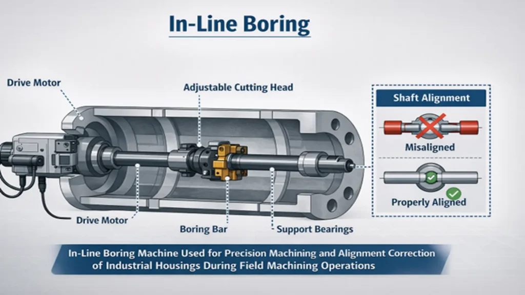
When misalignment involves internal housings, such as valves or pump casings, in-line boring is required.
This procedure machines internal surfaces using the common axis of the system as reference. It is especially used in:
- Large-diameter valves
- Pump bodies
- Vessel connections
Field machining through boring corrects eccentricities that could generate additional operational stresses.
Technology applied to portable machining
The evolution of portable CNC equipment has expanded the capabilities of field machining in large diameters and confined spaces.
Repairs performed through field machining are part of maintenance strategies used in modern pipeline integrity technologies within industrial facilities.
These systems incorporate:
- Electric or hydraulic drives
- Micrometric depth control
- Interchangeable cutting tools
- On-site concentricity adjustment
Precision depends on correct fixation and vibration control during operation.
Operational safety during plant shutdown
Field machining interventions require planning under industrial safety protocols.
Key aspects:
- Energy isolation (lockout/tagout)
- Atmosphere control
- Industrial risk management
A proper risk assessment reduces downtime and prevents operational incidents.
Industry and training in field machining
Field machining is a specialized discipline within industrial maintenance that requires geometric precision, metrological control, and regulatory compliance in critical assets.
International industrial reference
International companies such as TEAM Industrial Services have developed technical capabilities to perform facing, alignment, and boring in critical assets under regulatory criteria, integrating high-precision portable technologies and on-site dimensional verification.
Technical training and required competencies
Personnel training is essential to ensure reliable results. Required competencies include:
- Interpretation of ASME B16.5 and Section VIII
- Knowledge of ASME B31 codes
- Dimensional metrology
- Surface roughness control
- Industrial safety management
In addition to practical experience, an academic foundation in precision machining strengthens the understanding of geometric tolerances and dimensional control.
Technical institutions such as Ranken Technical College Precision Machining Technology include training in machine tool operation, CNC cutting processes, and metrological verification.
Mechanical engineering and industrial maintenance programs complement this training by providing foundations in structural analysis, advanced manufacturing, and geometric control applied to critical assets.
Conclusions
Geometric control of flanged joints is essential for the mechanical integrity of industrial assets. Deviations in flatness, runout, or roughness can compromise sealing even when the design complies with standards.
Field machining allows surfaces to be restored under criteria compatible with ASME B16.5 and associated codes, reducing downtime and avoiding unnecessary replacements.
In this context, Inspenet promotes the dissemination of independent technical knowledge focused on mechanical integrity and world-class maintenance in the energy and industrial sectors.
References
- American Petroleum Institute. (2016). Damage mechanisms affecting fixed equipment in the refining industry (API RP 571). API Publishing.
- American Society of Mechanical Engineers. (2022). ASME B16.5: Pipe flanges and flanged fittings. ASME.
- American Society of Mechanical Engineers. (2020). ASME B31.3: Process piping. ASME.
- American Society of Mechanical Engineers. (2021). ASME Boiler and Pressure Vessel Code, Section VIII – Rules for construction of pressure vessels. ASME.
- American Society of Mechanical Engineers. (2019). ASME PCC-1: Guidelines for pressure boundary bolted flange joint assembly. ASME.
- American Society of Mechanical Engineers. (2022). ASME PCC-2: Repair of pressure equipment and piping. ASME.
- Bolton, W. (2015). Mechanical science (5th ed.). Routledge.
- Moss, D. R., & Basic, M. (2013). Pressure vessel design manual (4th ed.). Gulf Professional Publishing.
- Peters, R. W., & Timmerhaus, K. D. (2019). Plant design and economics for chemical engineers (6th ed.). McGraw-Hill.
- Tubular Exchanger Manufacturers Association. (2019). Standards of the Tubular Exchanger Manufacturers Association (TEMA). TEMA.
Frequently Asked Questions (FAQs)
What flatness tolerance does ASME B16.5 require?
The standard defines face dimensions and characteristics but does not specify a single maximum flatness value.
What Ra roughness is required for RF flanges?
Between 125 and 250 µin (≈3.2–6.3 µm Ra).
When is in-line boring required?
When internal misalignment or eccentricity exists in housings.
Can any flange be machined on site?
Not always. Remaining thickness and compliance with the applicable code must be verified.