Table of Contents
Flanged joints are highly relevant elements for connections between pipes, equipment and accessories in industrial systems in addition to facilitating their assembly and disassembly. However, the installation and maintenance of these seals present a number of challenges that can affect their performance and the operational efficiency of the entire system.
In this paper, we will explore common challenges faced in the selection, installation and maintenance of flanged joints in the industry, as well as recommended solutions to effectively address these challenges. by providing a reliable seal.
What are Flanged Joints?
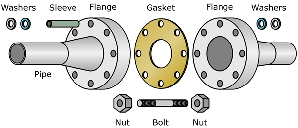
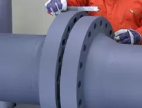
It is a coupling system used to join two pipe sections, pipes with equipment or pipes and fittings. This system allows the assembly and disassembly of the above mentioned parts without destructive operations, thanks to a circumference of holes through which bolts or connecting studs are mounted. A flanged joint consists of two flanges, a seal gasket between the two flanges, studs or bolts and washers1 as shown in Figure 1.
Flanged joint design
Designing these types of joints is an important process in mechanical engineering, as these joints are commonly used to connect piping, equipment and components in industrial systems processing and fluid distribution systems. The following is an overview of the steps involved in the design of a flange gasket:
Application requirements
Start by understanding the application-specific requirements for the flange gasket. This includes the type of fluid to be transported through the system, pressure, operating temperature, external environment, and flange size and rating, among other factors.
Material selection
Choose the appropriate flange gasket materials based on the requirements of the application. Common materials include carbon steel, stainless steel, rubber, PTFE (polytetrafluoroethylene), graphite, among others. Material selection should consider chemical compatibility, sealability, temperature and pressure resistance.
Dimensioning
Calculate flange joint dimensions, including inside and outside diameter, thicknesses, flange hole diameters and bolt or stud length and diameter. This is generally done in accordance with specific norms and standards such as ASME B16.21/B16.1/B16.5 or ASME/ANSI B16.47. These parts are normally manufactured from forged and machined or cast materials. They are pressure rated and are expressed in pounds per square inch (PSI).
Type of gaskets
There are several types of flange gaskets, the designer must select the most suitable type for the specific application according to the required specifications and tolerances. The most common types are:
- Welding Neck Flanges (WN – Welding Neck)
- Slip-On Flanges (SO – Slip-On)
- Threaded flanges (TH – Threaded)
- Lap Joint Flanges (LJ – Lap Joint)
- Flanges with seat for welding (SW – Socket Welding)
- Blind flanges (BL – Blind)
- Electrical insulation flanges
Flange face type
The types of faces determine both the gaskets required to install the flange and the characteristics related to the seal created. Common face types include:
- Flat Face (FF): Has a flat, even surface combined with a Full Face gasket that contacts most of the flange surface.
- Raised Face (RF): These flanges have a small raised section around the bore with an inner circular gasket.
- Ring gasket face (RTJ): Used in high pressure and high temperature processes, this type of face has a groove in which a metal gasket is seated to maintain the seal.
- Tongue and Groove (T&G): They have matching grooves and raised sections. This design helps the flanges to self-align.
- Male and Female (M&F): Similar to tongue and groove flanges, but using a pair of grooves and raised sections to secure the joint. However, unlike tongue and groove flanges, they retain the gasket on the female face, which provides more precise placement.
Finishes or roughness
The face types also offer different finishes or roughness. Choosing the right roughness is important as it will determine the optimum gasket for a reliable seal. In general, smooth faces work best with metal gaskets, while rougher faces help create stronger seals with soft material gaskets.
Sealing calculations
Performs calculations to ensure that the flange gasket will provide adequate sealing under the anticipated pressure and temperature conditions. This may include material strength analysis, joint compression calculations and leak testing.
Parasitic loads
Parasitic loads, such as vibration and thermal loading, can affect the integrity of bolts and flanges, so it is important to take these into account during design and installation.
Testing and validation
Prior to installation, it is important to test and validate the flange gasket to ensure its performance and reliability. This may include leak testing, pressure resistance testing and compression testing.
Inspection of flanged joints
Flanged joints can be inspected in service or during the assembly process.
Flanged joints Inspection in service
For this type of evaluation, it is recommended to evaluate the three components of the board. following the steps below:
- First, perform a general visual inspection (VT) of the entire flanged joint to determine macro damage or deviations and possible fluid leakage.
- Gaskets: Perform direct visual inspection (VT) to verify that the gasket does not have product leakage from this part, inspect the condition of the visible parts of the gaskets and that they comply with the specifications required by the service, depending on the temperature, pressure and type of fluid. As this evolution is limited only to what is accessible, it is possible to define if the material is metallic or not, if the thickness is adequate and if there is a packing degradation process.
- Stud bolts and nuts: Inspect the visible parts of these elements to verify that the dimensions are in accordance with the pressure class (Rating) of the flanges, as determined by the standard under which they were manufactured (For example, ASME B16.21/B16.1/B16.5 or ASME/ANSI B16.47, among others), and also verify the level of corrosion that these elements may have.
- Flanges: Evaluate the condition of the visible parts of the flanges to determine corrosion levels. Verify, supported by the stamping on the flanges, that the flange types, materials and maximum allowable pressure are in accordance with the service requirements, according to the design. Also check that the parallelism and eccentricity are within the allowed tolerances, for which we can rely on the ASME PCC-2 standard.
Inspection of flanged joints that are disassembled or in the process of being assembled
- Before starting the assembly of the flanged joint, the Inspector must request and know the design specifications of the pipe or pipe class and the technical data sheet of each of the parts. With this backup information, the parts that make up the flanged joint are evaluated and released if they meet the following requirements.
- Gaskets: Evaluate metallic, non-metallic or combined gaskets and verify that they meet design specifications based on flange type, material, temperature, pressure and fluid type.
- It is not acceptable to reuse gaskets, except those used in ring joint face joints (RTJ) which may be reused after being reconditioned in a manner consistent with the original specification.
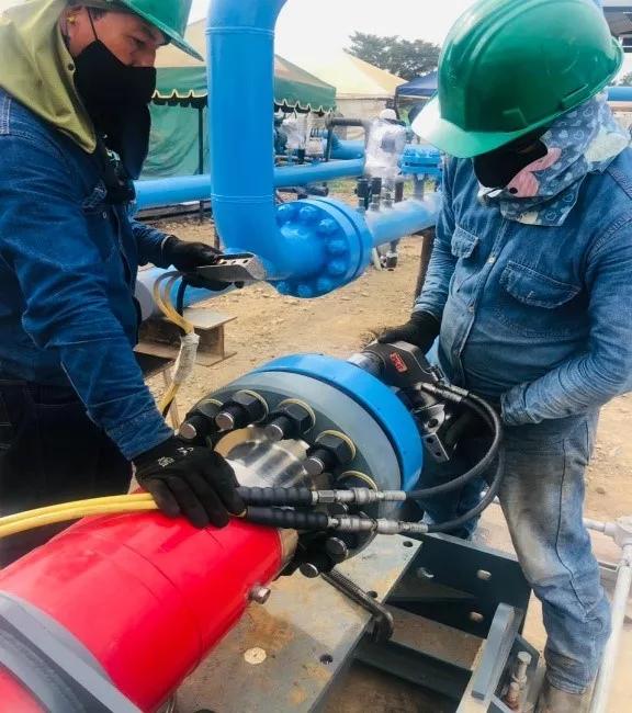
- Studs, bolts and nuts: Inspect these elements and verify that they comply with the design specifications (material, diameters, length, thread pitch and nut thickness), that the dimensions are in accordance with the diameters and pressure class (Rating) of the flanges, as determined by the standard under which they were manufactured (For example, ASME B16.21/B16.1/B16.5 or ASME/ANSI B16.47, among others). An additional point to consider when determining bolt or stud lengths is the thickness of the washers and that, for the use of tensioning machines or tools, the bolts or studs must extend at least one time their diameters beyond the outside face of the nut on the side where the tensioner will be placed as shown in Figure 2.
Excessive thread protrusion can make future disassembly of the joint difficult due to corrosion or damage in those areas, therefore, thread protrusion should be minimized.
It should be verified that lubrication is liberally and thoroughly applied to the threads of the nuts and both ends of the bolts. The lubricant reduces the coefficient of friction and results in less torque required to achieve a given tension, improves the consistency of the load achieved from bolt to bolt within the joint, and aids in assembly. Lubrication should be performed regardless of the tightening method used.
How to inspect a flange?
Flanges should be inspected as follows:
- Verify in the stamping of the flanges that they comply with the design requirements according to the type of flanges, type of fluid, materials and pressures,
- Evaluate the entire internal and external surface to determine possible corrosion levels.
- Check the cleanliness of the packing contact face. This area must be completely clean, free of any substance or elements.
- Inspect the surfaces of the flanges in contact with the gasket for possible damage due to corrosion, scratches or dents. Damage located on the gasket surface has an acceptance level established by ASME PCC-1 in appendix D of the (Guidelines for allowable gasket contact surface flatness and defect depth) and this is determined by its location and magnitude.
- Verify that the roughness of the surfaces in contact with the gaskets comply with the recommendations of ASME PCC 1.
Adjustment or tightening of studs and bolts
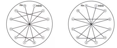
There are several methods for tightening bolts and studs, such as: hand spanners, impact spanners, pneumatic torque tools, tensioning tools, among others. ASME PCC 1 establishes the loads and limitations of each of these3. The sequence of the tightening pattern of bolts and studs is done in a linear way following the scheme shown in figure 3.
Flanged Joints installation and maintenance
Flanged joints are very important devices for preventive and corrective maintenance operations, as they facilitate relatively simple assembly and disassembly of equipment, piping and components, facilitate quick access to parts in need of repair or replacement, reduce time during maintenance operations, improve operational availability and reduce costs.
The assembly and disassembly of flanged joints requires a lot of precision, trained personnel and compliance with design specifications and standards such as ASME PCC-2 which determines everything related to the maintenance of flanged joints. Some of the activities to be considered in maintainability are the following:
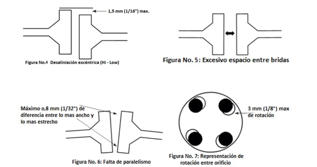
- Precise alignment: One of the main challenges during the installation of flanged joints is to achieve precise alignment between the flanged joint components. Lack of proper alignment can cause stresses in the joint and result in leaks. Figures 4, 5, 6, 7 and 8 show the types of misalignment with their tolerances and an actual example of misalignment3.
- Proper bolt torque: Lack of proper torque can cause insufficient load on the joint, resulting in leakage or even permanent deformation of the joint.
- Contamination during installation: Contamination from dirt, grease or other contaminants during installation can compromise the integrity of the gasket and affect its ability to seal effectively.
Considerations for the installation of flanged joints
- Alignment procedures: Implementing proper alignment procedures during installation, such as the use of accurate alignment devices and measurement techniques, can ensure optimal alignment between flanges.
- Torque control: Use calibrated torque tools and follow manufacturer’s recommended torque values to ensure proper loading on flange bolts. In addition, consider the use of controlled pre-loading techniques to improve torque uniformity on the bolts.
- Clean installation procedures: Implement clean installation procedures to avoid joint contamination. This may include proper cleaning of flange surfaces and the use of clean tools and equipment during installation.
- Minimize potential leakage: Leakage can occur due to a variety of reasons, such as gasket deformation, flange damage, insufficient bolt torque or contamination. Detecting and repairing these leaks in a timely manner is crucial to avoid product losses and ensure personnel safety.
- Limited access: In some industrial applications, limited access to flanged joints can make proper maintenance difficult. This may require the use of specialized equipment or the development of specific maintenance procedures to ensure safe and effective access to the joints.
Hot Stud and Screw Replacement
Hot bolt replacement involves replacing the studs or bolts of flanged joints while the equipment or piping is in operation. This process is highly risky and requires meticulous planning and the following of specific procedures to ensure the safety and integrity of personnel and equipment. Engineers should calculate the load resistance of the joint with missing and highly corrosive studs and this will determine if it is feasible to perform stud replacements one at a time.
The following are general steps for hot bolt replacement:
- Assessment of the situation: Before proceeding with replacement, it is crucial to assess the condition of the bolts and flanges to identify possible problems such as wear, corrosion or deformation.
- Risk Assessment: Performs a risk assessment specific to the task of hot stud or bolt replacement, identifying potential hazards and developing strategies to mitigate them.
- Personal Protective Equipment (PPE): Ensure that the required safety measures, including the use of appropriate personal protective equipment (PPE) and compliance with established safety procedures.
- Personnel training: Ensure that all personnel involved in the replacement are properly trained and have the necessary experience to perform the task safely and efficiently.
- Preparation of the work area: A safety perimeter should be established around the work area and ensure that all applicable safety regulations are complied with. In addition, it is important to have the proper personal protective equipment.
- Selection of tools and equipment: Select the appropriate tools and equipment for cutting and installing the studs, taking into account factors such as size, material, flange location and parasitic loads exerted by the tool or equipment.
- Post-replacement inspection: Perform a thorough inspection after replacement to verify the integrity of bolts, flanges and gaskets, and to ensure that there are no leaks or defects that could compromise the safe operation of the equipment.
Conclusions
Proper installation and maintenance of flanged joints is critical to ensure the integrity and efficiency of industrial systems. By addressing common challenges associated with these joints, such as precise alignment, torque control and proper material selection, companies can improve the reliability of their operations and minimize the risk of leaks and failures. By following recommended solutions and adopting proactive maintenance practices, flanged joints can play their role effectively in a wide range of industrial applications.
References
- MEP SKILLS; “Basic instruction for assembling a flange joint”; https://www.mepskills.com/2023/08/Assembling%20a%20Flange%20Joint.html.
- Company. Imsac Sas; https://imsacsas.com/equipos-de-torqueo-hytorc/
- (APPENDIX F “Alternatives to legacy tightening sequence/pattern”) del ASME PCC 1.