
Table of Contents
- Introduction
- What is ASME B31.3? scope and applicability
- Quick Summary: What’s new in ASME B31.3 (2024)
- Core design requirements in ASME B31.3
- Material selection and compatibility in ASME B31.3
- Fabrication, inspection & wwelding standards
- Pressure testing or hydrostatic testing under ASME B31.3
- Fluid service categories and their impact
- Pipe support spacing and system integrity
- Latest edition of ASME B31.3: What’s new?
- Benefits of using ASME B31.3
- Who uses ASME B31.3 and where?
- Common misconceptions and interpretation challenges
- Conclusions
- References
Introduction
In the world of industrial infrastructure, piping systems serve as the lifeblood of facilities in the oil & gas, petrochemical, chemical, and pharmaceutical industries. These systems transport critical fluids—often hazardous—under high pressures and temperatures, making their safe design, construction, and maintenance a top priority.
To ensure consistency and safety across such operations, the American Society of Mechanical Engineers (ASME) has established a series of codes. Among them, ASME B31.3 stands out as the primary standard for process piping, defining comprehensive requirements that govern the lifecycle of piping systems in processing environments. It is one of the most widely referenced documents globally for code for pressure piping systems operating in complex industrial settings.
ASME B31.3 provides detailed tables of allowable stress values, derived from material properties and safety factors. These stresses are critical for calculating pipe wall thickness and ensuring proper structural quality control, using formulas that incorporate internal pressure, pipe diameter, allowable stress, corrosion allowance, and manufacturing tolerance.
What is ASME B31.3? scope and applicability
In the world of industrial infrastructure, piping systems serve as the lifeblood of facilities in the oil & gas, petrochemical, chemical, and pharmaceutical industries. These systems transport critical fluids—often hazardous—under high pressures and temperatures, making their safe design, construction, and maintenance a top priority.
To ensure consistency and safety across such operations, the American Society of Mechanical Engineers (ASME) has established a series of codes. Among them, ASME B31.3 stands out as the primary standard for process piping, defining comprehensive requirements that govern the lifecycle of piping systems in processing environments. It is one of the most widely referenced documents globally for code for pressure piping systems operating in complex industrial settings.
ASME B31.3 offers engineers, designers, fabricators, and inspectors a structured framework covering design, material selection, fabrication, examination, and testing. Its global recognition not only ensures regulatory compliance but also reinforces process safety, reliability, and asset performance. This article explores the full scope of ASME B31.3, how it differs from other piping codes, and why it remains indispensable in modern industrial operations.
Quick Summary: What’s new in ASME B31.3 (2024)
- Revised allowable stresses based on updated material data
- Risk-based inspection for welds
- Updated guidance for dissimilar metal welding
- Better classification of Category M fluids. Read more in Section 9 of this article.
If you want to better understand how the ASME B31.3 code is structured, this video provides a chapter-by-chapter overview based on the 2016 edition. Although there are changes in later editions—which we address later in this article—this version retains the foundational principles that remain relevant for the design, inspection, and quality control of process piping systems.
A walkthrough of the ASME B3.3 process piping code chapters.
Core design requirements in ASME B31.3
The design phase in ASME B31.3 is one of the most rigorous and technically critical aspects of the code, ensuring that process piping systems operate safely under defined service conditions. It addresses both the mechanical strength of the piping and its functional performance under variable operational loads.
The first step in design is the establishment of design pressure and design temperature, which form the basis for calculating other mechanical parameters. Design pressure is not merely the operating pressure; it is the maximum pressure a system may experience during normal operations, including surges. Likewise, design temperature considers the maximum expected metal temperature due to the conveyed fluid or environmental factors.
ASME B31.3 provides detailed tables for allowable stress values, derived from material properties and safety factors. These stresses account for long-term strength and are critical in determining pipe wall thickness, which is calculated using equations that incorporate internal pressure, pipe diameter, allowable stress, corrosion allowance, and mill tolerance.
The corrosion allowance is another vital aspect. Designers must anticipate material degradation due to fluid characteristics or environmental exposure. For instance, piping in acid-processing units or offshore platforms often requires higher corrosion margins to ensure integrity over time.
Additionally, external loads such as wind, seismic activity, and equipment weight must be considered, especially in overhead or unsupported piping. These are combined with sustained loads—including internal pressure and weight of the fluid—to determine whether the system meets ASME-defined stress limits.
Lastly, expansion and flexibility are essential in thermal systems. ASME B31.3 mandates flexibility analysis to assess movements from thermal expansion and contraction. Expansion loops, bellows, or anchors may be required to absorb displacement and prevent overstressing.
Together, these design considerations ensure that piping systems not only comply with process safety regulations but also maintain long-term mechanical reliability and code compliance.
Material selection and compatibility in ASME B31.3
Material selection in ASME B31.3 is more than a matter of cost or availability—it is a technical decision that directly impacts safety, corrosion resistance, and system longevity. The code permits the use of metallic and non-metallic materials that comply with ASME and ASTM standards, ensuring consistency in performance under defined pressures and temperatures.
For metallic systems, commonly used materials include carbon steel (e.g., ASTM A106, A53), stainless steels (e.g., A312 TP304/316), and alloy steels (e.g., P11, P22), depending on service temperature, fluid aggressiveness, and pressure class. ASME B31.3 requires that the material properties be documented and traceable, and often imposes restrictions on their use in specific services like Category M fluid systems (highly hazardous).
The code also allows for non-metallic piping, such as HDPE (high-density polyethylene), particularly in low-pressure, non-hazardous applications. However, such materials are subject to limitations in terms of pressure-temperature ratings and are not suitable for high-temperature or high-pressure fluid systems.
Compatibility between pipe materials and the process fluid is a fundamental consideration. Chemical resistance, risk of stress corrosion cracking, thermal expansion coefficients, and long-term degradation under pressure must all be evaluated. This alignment ensures the piping system remains mechanically sound and chemically stable throughout its design life.
Fabrication, inspection & wwelding standards
ASME B31.3 emphasizes quality control during fabrication, especially in critical process piping systems where failure could result in catastrophic outcomes. The fabrication phase encompasses welding, fit-up, inspection, and dimensional control, ensuring that installed systems comply with the approved design.
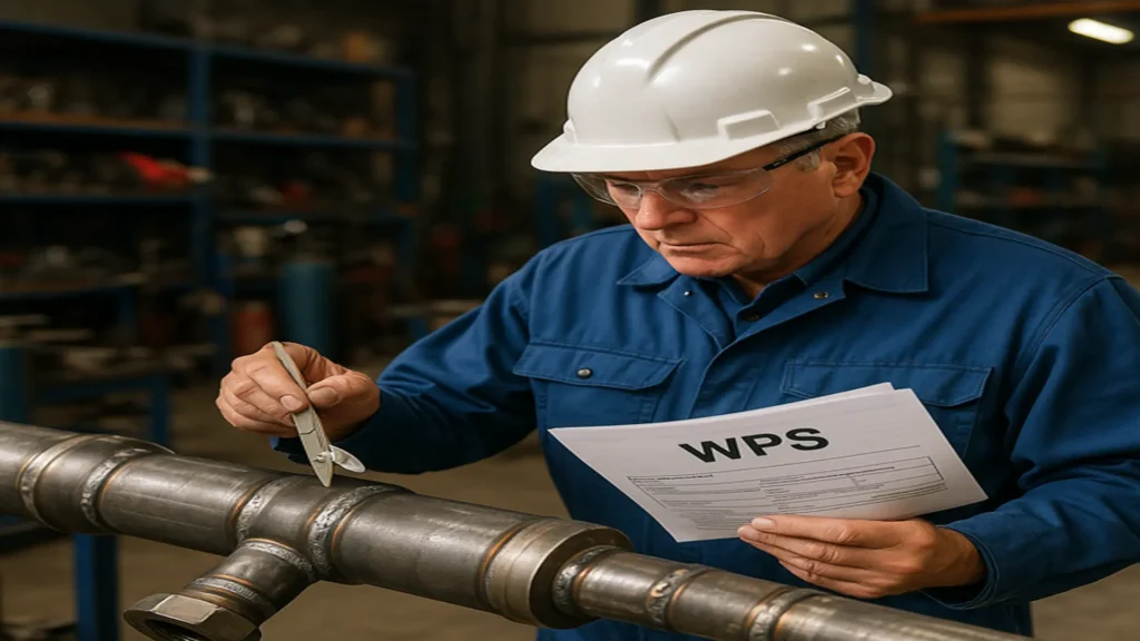
Welding procedures and welder qualifications must adhere to ASME Section IX, and every weld must be executed according to pre-approved Welding Procedure Specifications (WPS). The code also sets tolerances for desalineación (misalignment), with clear guidelines for pipe alignment and weld bevel preparation, especially when joining dissimilar pipe sizes or wall thicknesses.
Post welding, the inspection and examination requirements include visual inspection as a primary method for detecting surface defects, along with magnetic particle testing (MT), liquid penetrant testing (PT), and radiographic testing (RT), which plays a crucial role in identifying internal flaws and ensuring weld quality in critical joints. For systems involving Category D fluids (non-hazardous, low-pressure), inspections may be less stringent, while high-risk services demand 100% radiographic coverage on butt welds, in accordance with ASME B31.3 radiographic requirement standards.
The code mandates hydrostatic testing, often misnamed as “ASME B31.3 hydrostatic testing”, to verify the integrity of the system before commissioning. This test usually requires 1.5 times the design pressure, held for a defined duration with no observable leaks. Alternative methods such as pneumatic tests may be used in special cases but require heightened safety measures.
Together, fabrication standards and inspection protocols in ASME B31.3 create a quality assurance framework that minimizes defects, validates structural integrity, and ensures operational safety.
Pressure testing or hydrostatic testing under ASME B31.3
ASME B31.3 mandates that all process piping systems undergo a pressure test prior to being placed in service to verify mechanical integrity and leak-tightness. The hydrostatic test is the default and most widely used method due to its safety and effectiveness.
The hydrostatic testing procedure involves filling the piping with water or other non-hazardous liquid and pressurizing it to 1.5 times the design pressure. This pressure must be maintained for a minimum duration of 10 minutes, although in practice it is often held longer to detect potential leak points or weaknesses, especially at joints and welds. This answers the common question: “How long does a hydrostatic test last?”—while 10 minutes is the code minimum, extended testing is often applied depending on service criticality.
When water is not viable, due to fluid compatibility or freezing risk, pneumatic testing may be used as an alternative. However, since gases are compressible and carry higher stored energy, ASME B31.3 requires stricter safety protocols, including leak detection under soapy water or bubble solution and appropriate barricading of the test area.
Exemptions from testing are allowed under certain conditions, such as very low-pressure systems or systems tested in segments, where radiographic testing may be used to complement or substitute hydrostatic tests under approved procedures. Regardless of the method, Leak test acceptance criteria are strict: no visible leakage is permitted at any joint or connection, and visual inspection of all accessible areas is required both before and after pressure testing to ensure complete system integrity.
This section ensures system integrity before commissioning and supports regulatory compliance and operational safety.
Fluid service categories and their impact
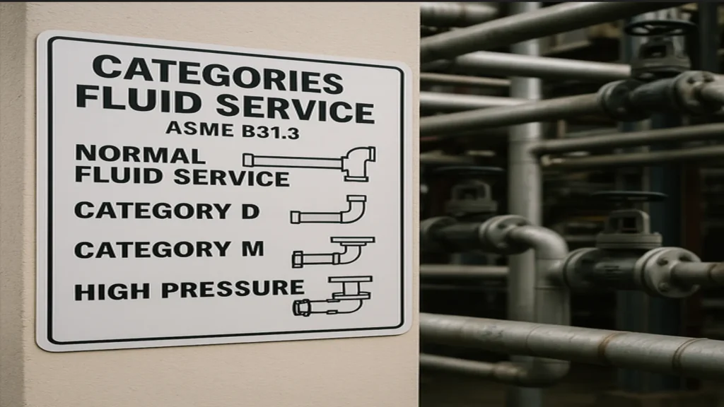
ASME B31.3 classifies piping systems into fluid service categories, each with distinct rules for design, fabrication, examination, and testing based on the hazard level of the fluid. Understanding these categories is fundamental to safe system design.
Normal fluid service: This is the default classification and applies to most industrial fluids that are not overly hazardous. Design and inspection rules here follow the baseline requirements of the code.
Category D: Applies to non-hazardous, low-pressure and low-temperature fluids such as water or compressed air. Piping under Category D is subject to reduced examination and testing requirements, often allowing visual inspection alone to confirm fit-up quality and compliance in low-risk applications.
Category M: Reserved for fluids that are highly toxic or hazardous to personnel even in small leaks (e.g., hydrogen sulfide, lethal gases). This category imposes stringent requirements, including 100% radiographic testing, increased fabrication scrutiny, and meticulous leak testing to validate the structural soundness of all welded joints.
High pressure fluid service: Defined by design pressure above 7000 kPa (1000 psi), this category applies to severe service such as high-pressure reactors or offshore injection lines. The code requires detailed stress analysis, advanced NDE methods, and enhanced fabrication control.
Each fluid service category directly affects piping wall thickness, allowable materials, welding procedures, and inspection criteria—making classification a critical early-stage engineering decision.
Pipe support spacing and system integrity
Proper pipe support is vital to ensure the structural integrity of process piping systems under both static and dynamic loads. ASME B31.3 provides guidance and reference tables for pipe support spacing, which vary based on pipe material, diameter, wall thickness, and service conditions.
As a general rule, heavier pipes and high-temperature systems require closer support spacing to limit sagging, stress concentrations, and joint misalignment. For example, a 2-inch carbon steel pipe may require support every 3 meters (10 feet), while a plastic pipe or steam line of the same size may need tighter spacing due to expansion and lower stiffness.
The code references Appendix D and allows the use of engineering judgment and analysis tools (e.g., Caesar II) for complex systems. In high-vibration environments or systems exposed to thermal cycles, additional supports such as guides, anchors, or spring hangers may be required.
Ultimately, properly designed pipe support systems not only maintain alignment and prevent desalineación, but also contribute to long-term reliability and reduction in fatigue-related failures.
Latest edition of ASME B31.3: What’s new?
The 2024 edition of ASME B31.3, published by the American Society of Mechanical Engineers, continues its biennial revision cycle and introduces several key updates that directly impact the work of piping engineers, inspectors, and system operators.
Below are the most relevant technical changes:
- Updated Allowable Stress Values: Numerous allowable stress values for metallic materials have been revised, based on updated mechanical properties and finite element analysis (FEA) models. These changes affect pipe wall thickness calculations and material selection for critical services.
- Redefined Criteria for Severe Cyclic Conditions: The new edition offers a more precise definition of severe cyclic service, introducing specific thresholds for pressure/temperature variation and number of load cycles. This clarification improves the design assessment of piping systems subject to thermal fatigue, such as steam lines or batch processes.
- Clarification of Category M Fluid Classification: The criteria for classifying a fluid as Category M have been refined with practical examples and improved definitions of toxicity, exposure risk, and handling requirements. This directly impacts engineering documentation, material traceability, and inspection scope.
- Risk-Based Inspection for Welds: ASME B31.3 (2024) adopts a risk-based inspection (RBI) approach to define radiographic testing requirements, allowing partial substitution by advanced NDE methods such as Phased Array (PAUT) or TOFD, when technically justified.
- Extended Guidelines for Dissimilar Metal Welds: The edition includes enhanced guidelines for welding dissimilar metals, especially under thermal cycling and combined stress conditions. It addresses fusion zone control, filler material selection, and post-weld heat treatment recommendations.
- Expanded Nonmetallic Material Compatibility Tables: New compatibility tables have been added for nonmetallic piping (HDPE, PP, PVDF), including expanded temperature, pressure, and chemical resistance limits. This improves material selection for auxiliary systems and low-risk applications.
These updates reinforce the code’s commitment to safety, reliability, and alignment with modern industrial practices. Engineers and inspectors should ensure they are working with the latest edition to avoid regulatory and technical nonconformities.
Benefits of using ASME B31.3
The ASME B31.3 code is globally recognized and adopted across industries for its comprehensive framework in governing process piping systems. One of the key benefits of ASME B31.3 lies in its alignment with international safety standards, which enables smooth regulatory approvals and cross-border project execution.
By standardizing design, materials, fabrication, and testing practices, it helps organizations mitigate operational risks, reduce the likelihood of catastrophic failures, and ensure process safety throughout the plant lifecycle.
Additionally, the code promotes system reliability and durability, enabling improved asset lifecycle performance and reduced downtime by enforcing consistent protocols such as visual inspection during fabrication and maintenance cycles due to failures or non-compliance issues. Projects designed to ASME B31.3 are more likely to pass audits, reduce insurance risks, and maintain consistent operating performance in high-consequence industrial environments.
Who uses ASME B31.3 and where?
ASME B31.3 is the dominant standard used across multiple industries where pressurized fluid transport plays a critical role. Key adopters include the oil & gas, petrochemical, pharmaceutical, chemical, LNG, and power generation sectors.
The code is essential for mechanical and piping engineers, inspection bodies, quality assurance professionals, and EPC contractors involved in designing or evaluating complex piping networks.
Asset types governed by this code include refineries, gas processing terminals, chemical plants, and high-pressure laboratories. These facilities rely on B31.3 for both greenfield design and brownfield modifications, ensuring that new and existing systems meet code integrity and inspection criteria worldwide.
Common misconceptions and interpretation challenges
Despite its extensive adoption, ASME B31.3 is often misunderstood, especially by those unfamiliar with the distinctions between piping standards. One of the most frequent misconceptions is equating process piping with utility or building services piping, such as HVAC, potable water, or fire protection systems. These typically fall under other standards like ASME B31.9 or mechanical/plumbing codes, not B31.3.
Another confusion lies in overlapping code boundaries particularly between ASME B31.1 (Power Piping) and B31.3 (process Piping). While B31.1 governs piping associated with electric power generating systems, B31.3 is tailored for fluid transport in processing plants. However, in facilities like combined-cycle plants or cogeneration units, distinguishing where B31.1 ends and B31.3 begins can be challenging, requiring engineering judgment and a strong understanding of system functions.
There are also interpretation challenges when applying B31.3 in small-scale operations, pilot plants, or multifunctional facilities that blend process piping with general utility services. In such cases, code jurisdiction may not be clear-cut, often leading to partial or incorrect implementation.
Finally, international projects may face difficulties where local codes differ in philosophy or structure. Successful application demands not only technical understanding but also code literacy the ability to interpret clauses, footnotes, and non-mandatory appendices accurately. Misapplying or underappreciating these details such as the role of visual inspection in early defect detection can result in non-compliance, unsafe systems, or audit failures.
Conclusions
In modern industrial systems, piping infrastructure is more than just a network of conduits—it is the circulatory system of any process plant, moving critical fluids under varying conditions of pressure, temperature, and composition. Within this high-risk, high-performance environment, ASME B31.3 stands as the benchmark standard for ensuring that these systems are designed, built, and maintained with safety and efficiency at the forefront.
From oil refineries in the Middle East to biotech plants in Europe and LNG terminals in North America, the principles laid out in ASME B31.3 ensure that materials are selected properly, joints are welded and inspected rigorously using radiographic testing where applicable, and systems are pressure-tested before entering service. It integrates engineering logic, risk control, and regulatory alignment, serving both technical and legal purposes.
For engineers, project managers, inspectors, and asset owners, ASME B31.3 provides more than just code compliance—it offers a strategic tool for process integrity, reduced liability, and global interoperability.
In a world increasingly focused on process safety and reliability, mastering the principles of ASME B31.3 is not just a professional responsibility, but a crucial step toward sustainable, secure industrial operations.
References
- ASME. (2024). ASME B31.3: Process Piping, 2024 Edition. American Society of Mechanical Engineers. Recuperado de https://www.asme.org/codes-standards/find-codes-standards/b31-3-process-piping
- Becht Engineering. (2024). ASME B31.3 Process Piping – Changes in the 2024 Edition. Becht Blog. https://becht.com/becht-blog/entry/asme-b31-3-process-piping-changes-in-the-2024-edition
- ASME. (2023). Boiler and Pressure Vessel Code Section IX – Welding and Brazing Qualifications. American Society of Mechanical Engineers.
- International Society for Automation (ISA). (2020). Industrial Process Piping Systems. ISA Technical Reports.
- API – American Petroleum Institute. (2014). API 570: Piping Inspection Code. API Publishing Services.
- Eddyfi Technologies. (2022). Advanced Phased Array Ultrasonic Testing (PAUT) for Process Piping Applications. https://www.eddyfi.com