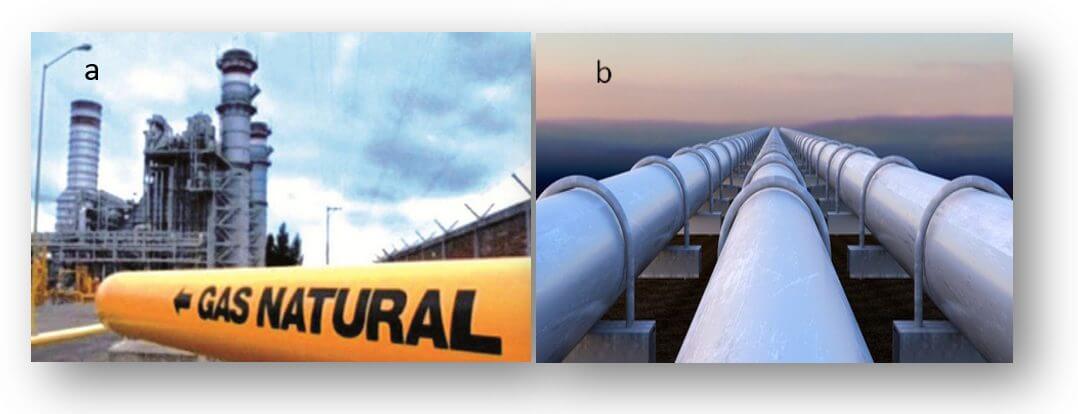
The transportation of natural gas requires ensuring the structural integrity of pipelines and the safety of the fluid being transported. To this end, companies implement integrity management programs that include inspection and periodic cleaning to remove impurities that could compromise operations. When damage, ruptures, or leaks occur, it is essential to implement corrective actions that reduce the risks of economic losses, equipment damage, and impacts on worker safety (API, 2013).
Currently, gas industries incorporate advanced technologies that allow for more accurate assessment of condition and extend their useful life. This article explores the main technologies applied in inspection, highlighting their advantages, limitations, and the strategic role they play in the reliability of fluid transport systems.
Pipe integrity assessment
Integrity assessment is one of the pillars of a management program. It allows for the identification of deterioration, calculation of remaining useful life, and decision-making regarding repairs or replacements. One of the most representative stages to consider in a Pipeline System Integrity Management Program (Figure 1) for the transport of hazardous fluids is the assessment of the integrity of the sections that make up a pipeline. This is done in order to identify the deterioration caused, ascertain its condition, determine its remaining useful life for continued service, and establish the need for measures such as repair or replacement.

It is important to perform preventive maintenance on gas pipelines to prevent or reduce problems that affect their integrity; one way to do this is by using tools for cleaning and internal inspection of the pipeline. Technologies used in the inspection of pipelines.
The API 1160 recommended practice establishes fundamental techniques such as:
- Hydrostatic testing.
- Direct threat assessment.
- Inline inspection (ILI or Smart Pigging).
These methodologies help minimize the risk of leaks, corrosion, and structural failures in gas pipelines (API, 2013).
Pipe inspection technologies
Hydrostatic test
The hydrostatic test is a method that guarantees the tightness of the pipeline and determines whether it can operate safely under the Maximum Operating Pressure (MAOP).
Procedure
- Removal of the service pipeline and purging of gas.
- Mechanical internal cleaning.
- Sealing of ends and filling with water.
- Pressurization to levels above operating pressure.
- Monitoring for a typical period of 8 hours.
- Repair of leaks and repetition of test if necessary.
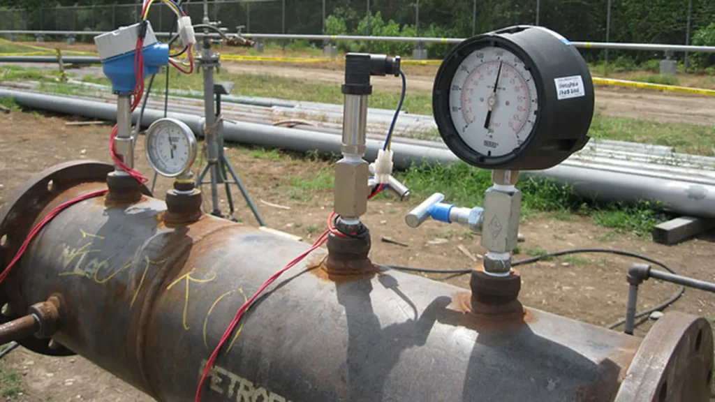
This procedure, regulated by API 1160 and ASME B31.8, applies to both new gas pipelines and repaired lines, ensuring the reliability of the systems (API, 2013). Figure 2 shows the installation for performing this test.

Direct threat assessment
Direct assessment is used to analyze specific threats such as internal corrosion and external stress corrosion cracking (SCC).
When segments are identified as critical, non-destructive techniques are applied to estimate the condition of the pipeline. However, access can be complex in areas such as river crossings, jacketed pipes, or hazardous areas (API, 2013).
In-line inspection with Smart Pigs
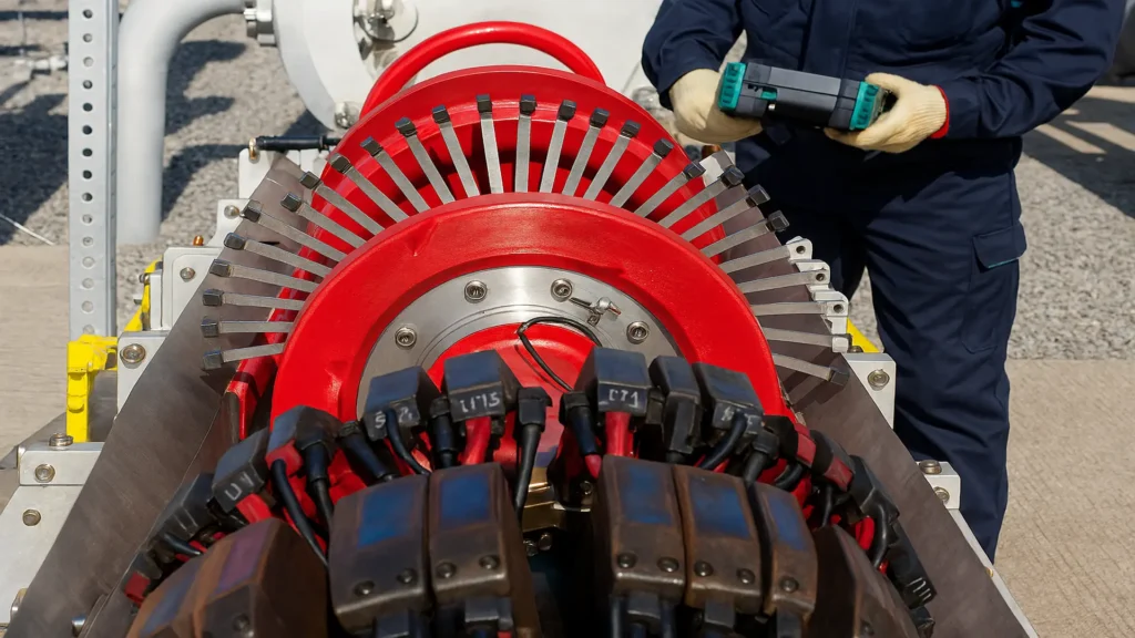
In-line inspection (ILI) or Smart Pigging is one of the most widely used technologies. It involves introducing devices that travel through the pipeline driven by the gas flow itself. Among the internal line inspection or in-line inspection (ILI) devices available are devices called “Smart Pigs,” which can be equipped with robotic cameras and sensors to check the thickness of the pipe and welds, and also detect corrosion failures (Figure 3).

Most commonly used technologies.
- Magnetic flux leakage (MFL).
- Ultrasound (UT).
- Electromagnetic-acoustic transducers (EMAT).
- Eddy currents (ET).
Smart pigs can detect corrosion, weld failures, and thickness variations. Their main limitation is that many older pipes were not designed to allow their use (API, 2013).
Quest Integrity’s InVista™ technology
The InVista™ tool, developed by Quest Integrity, is a high-fidelity ultrasonic smart pig designed for pipes considered “uninspectable.” InVista™ technology, based on ultrasound, represents an innovative option for evaluating the pipe or duct inspection program of industrial plants.
Advantages of InVista™ Technology
- Inspects 100% of the surface.
- Operates on pipes with multiple diameters and tight bends.
- Detects corrosion under insulation (CUI).
- Reduces costs by collecting data in a single pass.
- Compliant with API 570 and API 574 (Quest Integrity Group, 2020).
In addition, the information collected can be processed with LifeQuest™Pipeline software, allowing the remaining service life to be calculated using the API 579 Level 2 methodology (Quest Integrity Group, 2020).
Below is a video of the InVista device, courtesy of Quest Integrity Group.

Process Pipeline Inspection for Refineries and Chemical Plants.
Visual inspection with video cameras
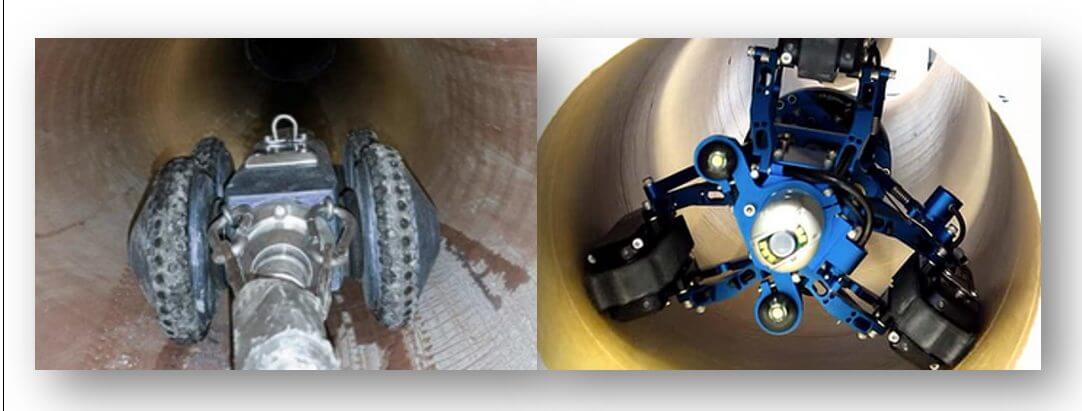
Pipe videoscopy is a remote inspection method in which cameras are inserted to record internal images (Figure 4).

Inspection procedure
- Excavation of access points along the line.
- Gas purging and sealing.
- Insertion of camera or video probe.
- Recording and analysis of images by specialists.
This method is useful for confirming visual defects in critical areas, although it does not detect hidden damage (API, 2016).
Comparison of inspection technologies
Table 1. Comparison of natural gas pipeline inspection technologies.
| Methodology & Technology | Main Application | Advantages | Limitations |
|---|---|---|---|
| Hydrostatic Testing | Check resistance and leaks | Proven and reliable method | Requires pipeline shutdown and service interruption |
| Direct Assessment | Detect internal and external corrosion | Non-destructive testing techniques | Limited access in certain segments |
| Smart Pigging | Identify internal defects | High accuracy, multiple sensor options | Not all pipelines are piggable |
| InVista™ | “Unpiggable” pipelines | Comprehensive and flexible inspection | Higher cost |
| Video Cameras | Internal visual inspection | Low cost, provides direct visual confirmation | Cannot detect hidden or subsurface defects |
Benefits of pipe inspection
Pipe inspection allows companies to anticipate failures, optimize maintenance, and ensure the safety of workers and industrial operations. Among its main benefits are:
- Early detection of damage: Identifies corrosion, cracks, or material loss before they become critical problems, reducing operational and economic risks.
- Extended service life:: By implementing timely corrective actions, premature wear is prevented and the reliability of fluid transport systems is improved.
- Regulatory compliance: Helps comply with international standards and local regulations, avoiding penalties and ensuring good operating practices.
- Optimization of maintenance costs: It allows for the planning of precise interventions, reducing emergency repairs and downtime.
- Improvement of industrial safety: It minimizes the risk of accidents and leaks, protecting workers and the environment.
Overall, inspection represents a significant strategy for any integrity management program, combining operational efficiency, safety, and sustainability.
Conclusions
Pipeline integrity management is essential for the safety and reliability of natural gas transportation. Technologies such as hydrostatic testing, direct evaluation, Smart Pigs, the InVista™ tool, and video cameras offer complementary solutions to extend service life and ensure operational safety.
Each methodology has advantages and limitations, so combining these techniques within a comprehensive program is essential to comply with international standards and minimize risks.
References
- American Petroleum Institute. (2013). API RP 1160: Managing System Integrity for Hazardous Liquid Pipelines. API Publishing.
- American Petroleum Institute. (2016). API 570/574: Piping Inspection Code. API Publishing.
- Quest Integrity Group. (2020). InVista™ Technology for Pipeline Inspection. Retrieved from https://www.youtube.com/watch?v=OLqqWq88GlM

