Table of Contents
Authors: Carlos Melo, Gerald Haynes, Jorge Vásquez, Alberto Janeta
Abstract
AC interference has become a growing threat to pipeline safety, especially with modern high- resistance coatings and increased proximity to High Voltage Alternating Current (HVAC) transmission lines. Grounding systems are implemented to mitigate AC effects, often using copper or zinc.
While zinc has historically been used to re- duce bi-metallic corrosion concerns, recent studies and field evidence show significant degradation of zinc in AC environments. This paper reviews the limitations of zinc as a grounding material, emphasizing findings from industry studies and standards, and discusses the environmental and operational implications.
1. Introduction
Pipelines are widely regarded as the safest method to transport oil and gas [1], [2]. How- ever, shared corridors with HVAC lines introduce AC interference risks, including corrosion and personnel safety hazards. Earlier assumptions underestimated AC corrosion, but field failures in Germany during the 1980s revealed its potential to damage coated pipelines even under Cathodic Protection (CP). These failures, despite CP polarization levels of -1.000 V, demonstrated the need for more rigorous AC mitigation strategies [3].
AC corrosion has been studied since the early 1900s. Initially, it was believed that corrosion from alternating current (AC) was negligible compared to direct current (DC) and that polarization through cathodic protection would prevent damage. However, this view changed with field experience and experimental data.
In particular, failures in low-resistivity soil challenged prior assumptions, highlighting that AC current densities above 20 A/ m2 can initiate corrosion, especially in high-impedance coatings. As pipeline coatings improved in dielectric strength, they became more susceptible to interference due to reduced leakage paths to ground. This, in turn, increased the importance of grounding system design for effective AC mitigation.
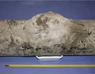
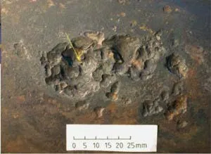
Figure 1: AC Corrosion Leak Site [3]
Figure 1 shows a field failure attributed to AC corrosion, where external bulging caused by corrosion product buildup eventually exposed the underlying metal loss and perforation. These visual indicators support laboratory findings and demonstrate the severity of AC interference.
The three types of AC interference that can affect a pipeline are Electromagnetic (Induc- tive Coupling), Electrostatic (Capacitive Coupling), and Conductive (Resistive Coupling) [4], [5]. In inductive coupling (Fig. 2a), the level of interference decreases with the sepa- ration between the HVAC conductors. Additionally, the magnetic field strength is directly proportional to the current that circulates in the HVAC conductors and inversely propor- tional to the distance between the conductor and the pipe. Inductive coupling interference normally peaks at discontinuity locations [3], [4].
In electrostatic coupling (Fig. 2b), two conductors separated by a dielectric material create a capacitor. The electromagnetic field between the HVAC line and the pipeline builds up electrical charge, which is stored in the capacitor (Fig. 3a) until a connection to the ground is made (Fig. 3b) [4], [5]. Finally, resis- tive coupling (Fig. 2c) occurs when a HVAC line sends a fault current to the ground. These faults generally occur during lightning, and even though the duration is measured in frac- tions of a second (milliseconds), fault currents can reach hundreds of thousands of amperes, which can be detrimental to the coating of the pipeline, the integrity of the pipe, and the safety of the pipeline personnel and the public [4], [5].
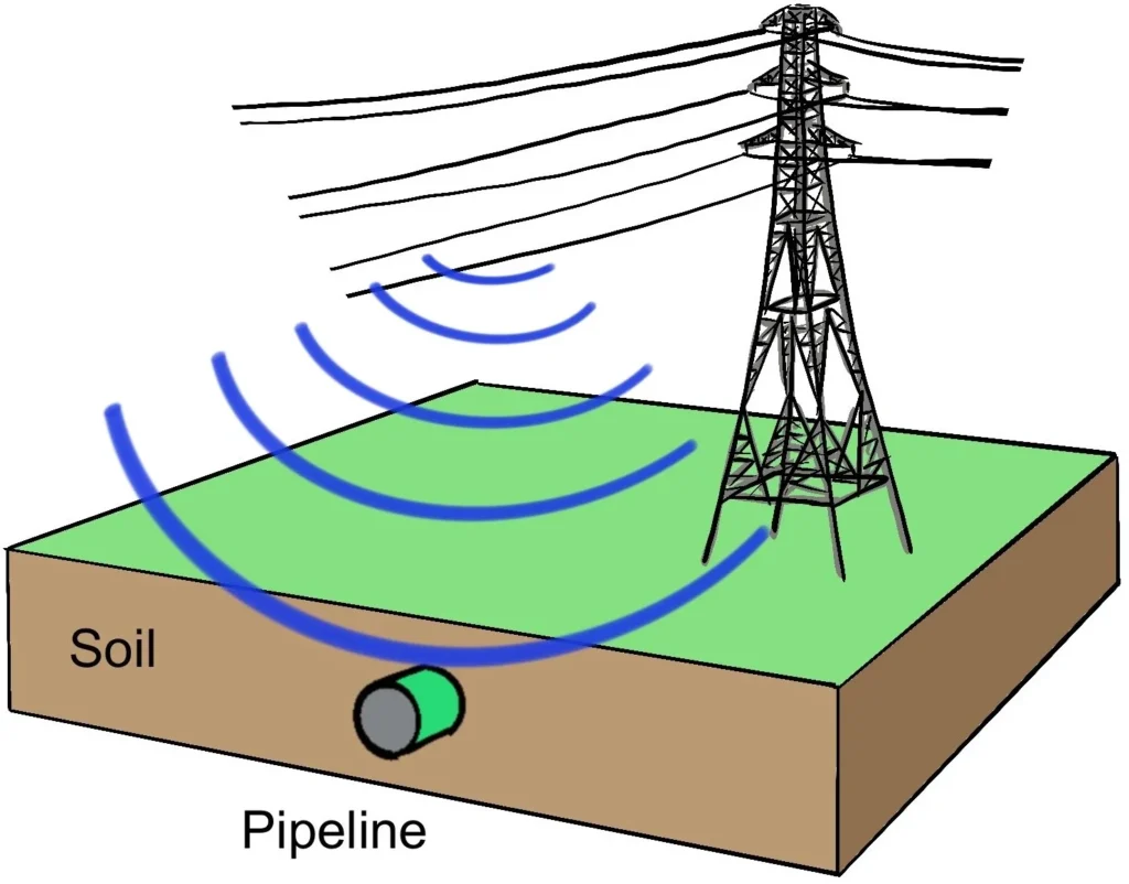
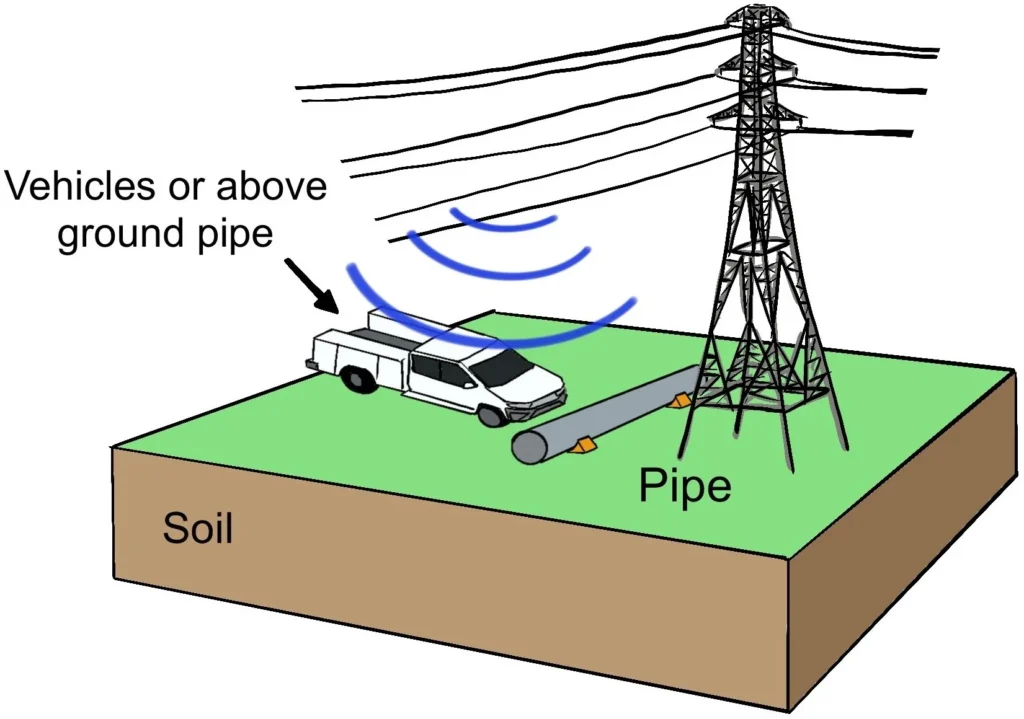
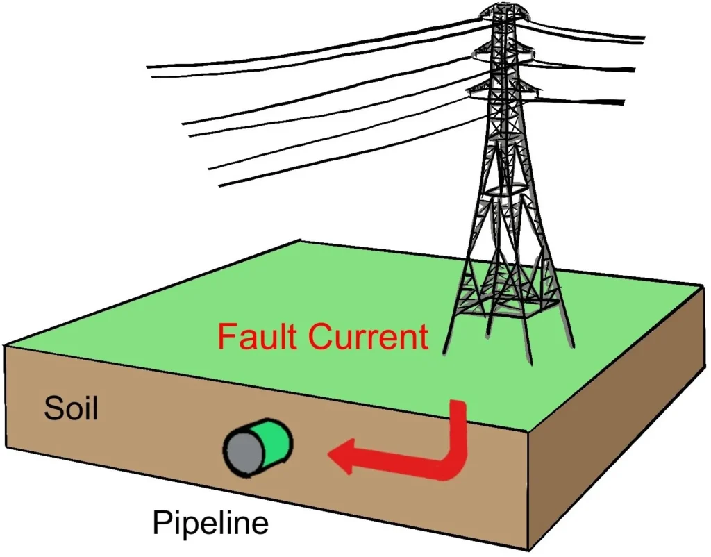
Figure 2: Types of AC Induced Interference on Pipelines
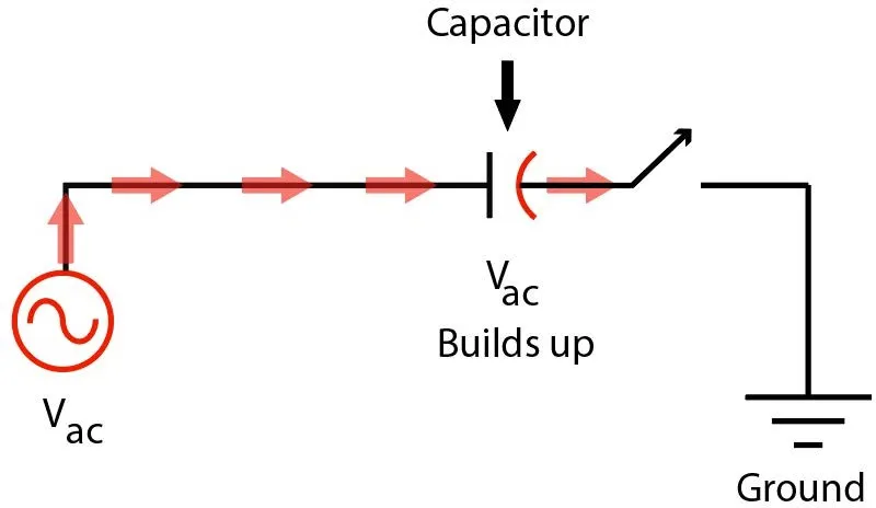
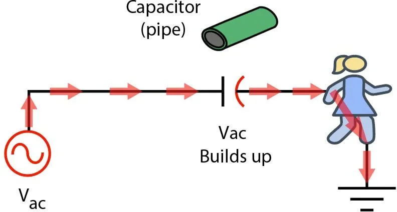
Figure 3: Capacitive effect in pipelines
2. AC Interference Evaluation and Mitigation
Pipeline operators evaluate interference using pipe-to-soil potentials, Longitudinal Electric Field (LEF)surveys, and soil resistivity [6], [7]. HVAC system data such as tower specs and current loads feed into Computer Aided Engineering (CAE) software, which simulates induced voltages and recommends mitigation.
Mitigation often involves installing grounding systems: horizontal or vertical rods con- nected via decouplers to the pipeline. Decouplers prevent CP current drainage while allowing AC faults to ground safely. Grounding material selection—typically copper or zinc—plays a critical role in long-term system integrity [8].
The Institute of Electrical and Electronics Engineers (IEEE) and European Norm (EN) standards provide criteria for acceptable voltage levels and current densities on pipelines. Typical mitigation goals include maintaining current density below 30 A/m2 and reducing AC voltage to less than 15 V under steady-state conditions. CAE models guide grounding placement to meet these thresholds.
Field validation using AC coupons ensures that pre- dicted performance matches reality. DC decouplers, required to fail safe, must isolate CP systems from the ground without compromising personnel safety during fault conditions.
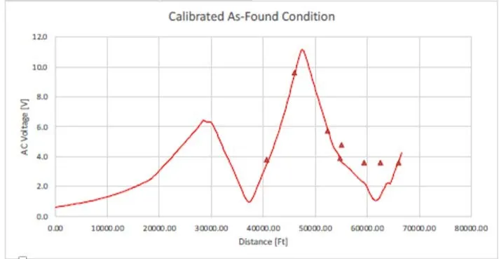
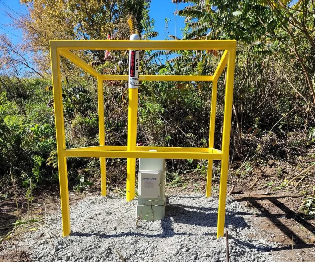
Figure 4: Design of AC Mitigation Systems
Figure 4 illustrates the use of modeled voltage gradients along a pipeline and the practical field implementation of a decoupler device to manage induced AC. Proper integration of both aspects is critical to reliable AC mitigation.
3. The History of Zinc for AC Mitigation
Copper was traditionally favored, but concerns over bi-metallic corrosion led to zinc’s adop- tion [9]. However, IEEE Std. 80 [10] and DIN 50929-3 [11] require soil testing to justify zinc use due to its potential corrosion in varying conditions.
These standards emphasize that zinc may only be acceptable when detailed testing con- firms stable corrosion behavior in the intended environment. The DIN standard, in particu- lar, includes classifications for soil aggressiveness and corrosion rates under various chemical compositions. Zinc often falls short in acidic or sulfate-rich environments and may passivate unpredictably in carbonate systems. Long-route pipeline projects face challenges with this requirement. Moreover, insufficient studies exist on zinc’s long-term behavior under continuous AC exposure. Backfill choices, passivation, alkaline and acidic environments, and CP interaction raise further concerns about zinc reliability.
Zinc can passivate in carbonate-forming and sulfate-rich soils, including those impacted by agricultural fertilizers, which are common in pipeline rights-of-way. In other conditions, zinc corrosion is exacerbated by chloride and sulfur-containing environments. Additionally, cathodic protection systems can increase alkalinity near zinc surfaces, promoting rapid dis- solution, yet this effect is often underestimated in practice.
In addition, operators have reported inconsistent field performance of zinc ribbon systems. In some locations, zinc remains largely intact after years of service. In others, severe pitting or total dissolution occurs in a fraction of the design life. This variability creates uncertainty and risk when planning mitigation programs.
4. Issues with Zinc for AC Mitigation
4.1. Case Study: NACE Paper 12828
This study reported corrosion rates of over 40 mpy in zinc exposed to corrosive soils, while copper under similar conditions corroded at less than 1 mpy [5]. scanning electron microscopy (SEM), energy dispersive X-ray spectrometry (EDS), and X-ray diffraction (XRD) confirmed white rust and corrosion layers 30–50 mils thick. Chlorine and sulfur compounds were present, exacerbating zinc deterioration. Figs. 5a and 5b present images of the severely corroded zinc ribbon [5].
This paper concluded that zinc is highly reactive in soils with a high chloride or sulfur content. Furthermore, the degradation of the backfill and poor field construction practices may contribute to the exposure of zinc to aggressive soil layers. The authors recommended that zinc must be voided unless extensive testing is performed to verify compatibility with site conditions.
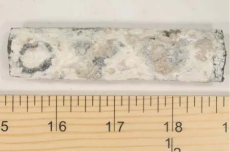
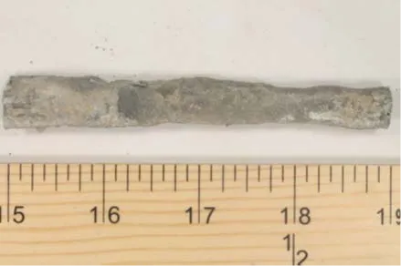
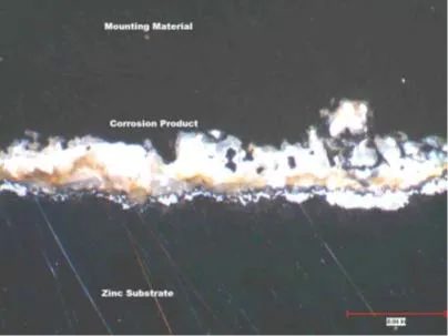
Figure 5: Findings from NACE Paper No. 12828 [5]
4.2. Journal Article: Corrosion Vol. 71, No. 6
The tests showed that the zinc corrosion rate increased from 6 mpy (no AC) to 32.7 mpy at 300 A/m2 AC current density [8]. Fig. 6a shows a plot of the corrosion rates of zinc as a function of the AC current density. As observed, there is a significant increase when the AC current densities approach 100 A/m2. AC oscillation damaged protective films, accelerated corrosion, and prevented passivation.
Electrochemical Impedance Spectroscopy (EIS) showed significant loss of film resistance, from 633 to 30 ohms. SEM images confirmed cracking and micropores in the film structure. Fig. 6b shows the corrosion product film after four days of exposure to 300 A/m2 of AC current density.
The article also explained that high AC densities not only corrode zinc faster but also destabilize the corrosion products that may initially provided some barrier to further attack. The result is a feedback loop where the corrosion accelerates over time. The absence of passivity under AC conditions makes zinc less predictable and less durable.
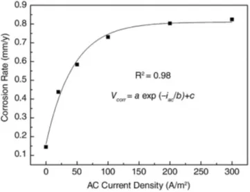
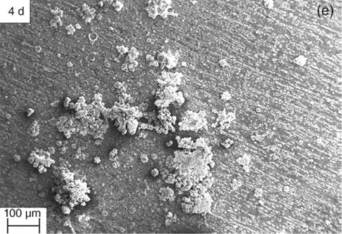
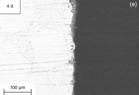
Figure 6: Data from Corrosion Journal [8]
4.3. Operator Experience and Environmental Concerns
Field data reveal frequent zinc failure near decouplers, where current densities exceed 100 A/m2 [5], [8]. CAE models confirm these elevated current zones. Zinc dissolution contam- inates soil and the high bioavailability of the metal raises ecological concerns. Excess zinc in soil is known to be phytotoxic and detrimental to yield quality [12]. With increasing regulatory attention, particularly in the EU, future restrictions on zinc use may also impact copper-based systems.
5. Conclusion
Zinc corrosion susceptibility under AC conditions presents a reliability and environmental risk to mitigation systems. Although IEEE allows zinc with soil testing, evidence from field failures and laboratory studies indicates that copper is generally more stable. Operators must carefully assess the selection of grounding material to ensure the longevity of the grounding system and environmental safety.
References
[1] Chen et al. (2019) study key indicators of reputation loss in oil and gas pipeline failures.
[2] Green & Jackson (2015) compare the safety of oil and gas transport via pipelines and rail.
[3] AMPP (2010) reviews corrosion rates, mechanisms, and mitigation in pipeline protection.
[4] Cheng (2021) discusses corrosion of pipelines and protection techniques.
[5] Zamanzadeh et al. (2019) explore AC interference corrosion and mitigation methods.
[6] AMPP (2019) addresses AC and lightning effects on metallic structures and corrosion control.
[7] AMPP (2018) assesses risks and mitigation for AC corrosion in cathodically protected pipelines.
[8] Tang et al. (2015) analyze zinc’s performance in AC mitigation.
[9] Woodberry (1983) investigates corrosion caused by electricity discharge from buried metals.
[10] IEEE (2015) offers guidelines for safety in AC substation grounding.
[11] DIN (2024) examines corrosion likelihood in buried and underwater pipelines.
[12] Kaur et al. (2024) review zinc behavior in soils and strategies for reducing toxicity.
This article was developed by Vecor Pipeline Integrity specialists and published as part of the fifth edition of Inspenet Brief magazine August 2025, dedicated to technical content in the energy and industrial sector.