
Introduction
Industrial processes require precision, safety and efficiency to ensure optimum performance. Flanges, although often overlooked, are essential accessories for the interconnection of pipelines, equipment and systems, ensuring the tightness and operation of complex systems. But what is a flange? How can such a simple element be fundamental to the flow of fluids in industrial plants and gas pipelines?
This article discusses the critical role of flanges in piping systems engineering, addressing their classifications, selection criteria and industrial applications. It examines the technical regulations governing their use and the importance of proper management to mitigate risks of failure, ensuring the structural integrity and operational performance of facilities.
What is a flange?
A connecting component, usually metallic, used to join two elements within a piping system, equipment or machinery. It establishes a hermetic joint between components of an installation, such as pipes, valves, pumps or heat exchangers. It has a discoidal geometry with perforations for bolting and the use of gaskets.
There are different types of flanges, the design of which depends on factors such as the type of fluid being transported, the pressure and temperature of the system, and the environmental conditions. In general terms, industrial flanges represent “links” within a piping system, facilitating the safe connection of its components and allowing efficient disassembly for maintenance or repair without the need to intervene in the entire installation.
Most flanges are made of metallic materials such as A105 carbon steel, 304 and 316 stainless steel, monel, inconel, chome moly, bronze and other alloys; however, some specific applications require the use of non-metallic flanges, such as reinforced plastics or glass-lined steel, and are mainly used in environments demanding high chemical resistance.
Flange face types
- Raised Face (RF): The most common type in the industry, characterized by a small raised section above the bolt circle, which allows the use of various packings and concentrates pressure in order to improve containment. The face height varies according to the pressure class, being 1/16“ for classes 150 and 300, and ¼” for higher classes, the typical surface finish is 125 to 250 µ in Ra.
- Flat Face (FF): The gasket surface is in the same plane as the bolt circle, they are frequently used on cast iron flanges and are not compatible with RF. ASME B31.1 provides guidelines for their use, especially with cast iron flanges.
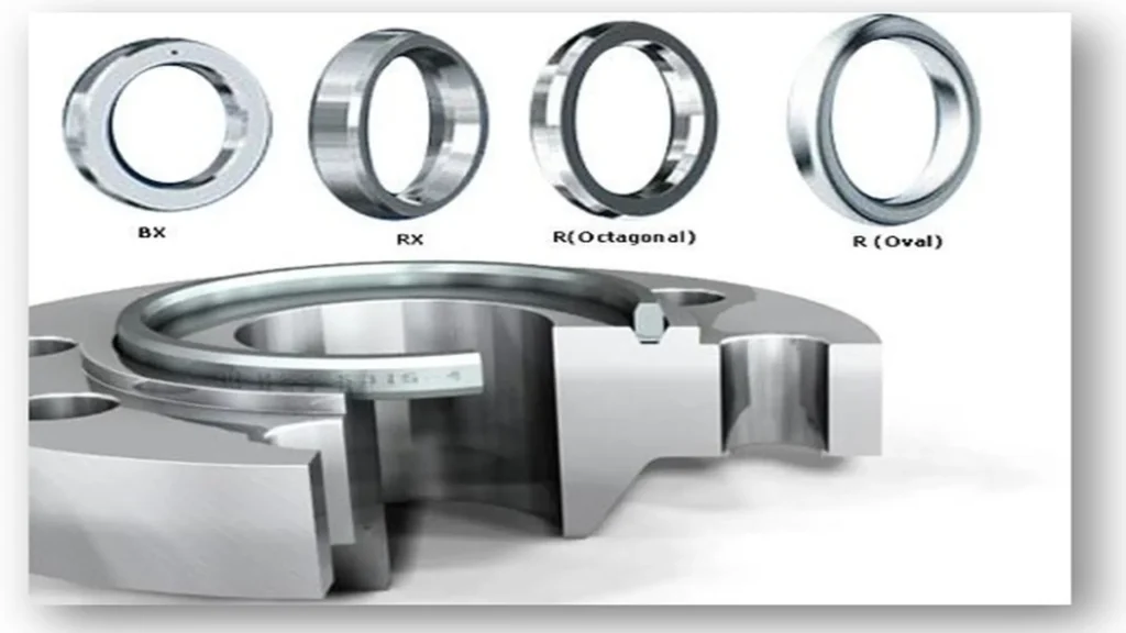
- Flanges with ring gasket (RTJ): They are designed for high pressure and temperature processes, they have machined grooves where a metal gasket or ring sits to maintain the metal-to-metal compression seal. These flanges use ring gaskets, such as R type (oval and octagonal), RX and BX.
Main standards for the use of industrial flanges
Standardization in the manufacture and use of flanges is necessary to ensure compatibility and safety. In America, the ASME/ANSI standards are the most widely applied, while in Europe, the German DIN EN 1092-1 standards are the most widely used.
American standards (ANSI/ASME/MSS)
- ANSI/ASME B16.5: The most widely applied standard worldwide. It specifies dimensions, materials, tolerances and tests for cast, forged or sheet metal flanges. It covers nominal diameters from 1/2“ to 24” in pressure classes from 150# to 1500#, and from 1/2“ to 12” in 2500#.
- ANSI/ASME B16.47 Series A: This standard covers large diameter steel flanges, from NPS 26 through NPS 60, in pressure classes from 150# to 900#. Series A, specifically, is based on API 605 flange dimensions, and are generally heavier and more robust than Series B flanges.
- ANSI/MSS SP-44: Specifies requirements for flanges used in thin-walled, high strength piping. Covers ranges from 12“ to 60” in pressure classes 150# to 600#, and up to 48” in 900#. Applies to weld neck and blind flanges only. Outside diameter and drilling template match ASME up to 36”, allowing use with valves and pumps built to those standards.
- ANSI/ASME B16.4: Includes the previous standard, complementing it with the pressure, temperature and material ranges of ASME B16.5. Class A is similar to MSS SP44, Class B matches API 605.
- ANSI/ASME B16.20: Specifies materials, dimensions and marking of rings for 1/2“ to 24” steel gaskets in pressure classes from 150 psia to 1500 psia, and up to 36” at 900 psia.
European standard (DIN)
- DIN EN 1092-1: It is the most widely used standard in Europe, specifying dimensions and requirements for steel flanges. This standard covers different types of flanges and pressures, adapting to industrial applications in the European continent.
How to identify a flange?
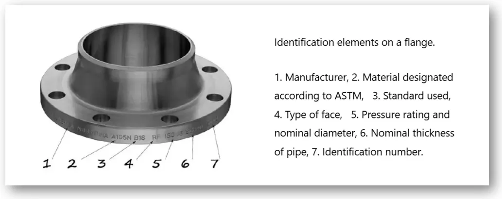
All flanges, including forged and cast flanges, are specifically marked with design characteristics, indicating service pressures, materials, dimensions, tolerances, marking, and flange testing. These are shown in the following image.
Types of industrial flanges
The most common types of flanges are listed below:
Welding neck flange
The weld neck flange features a tapered neck, which is joined to the pipe by a full penetration butt weld. The long tapered neck optimizes stress distribution, ensures a smooth flow transition and reduces turbulence, which improves the structural integrity of the connection.
They are used when stresses on the joint are maximum, such as in high pressure and temperature systems, in pipelines carrying corrosive or hazardous fluids, and in severe cyclic loading conditions. In addition, they are essential in applications where non-destructive testing (NDT) such as X-ray or ultrasonic testing is required to verify weld quality. Common services include steam, oil, gas and chemicals.
Technical characteristics
- Design standards: ASME B16.5 and ASME B31.3.
- Type of joint: Conical neck for butt welding.
- Materials of construction: Available in various materials depending on the application.
- Face types: Raised (RF), flat (FF) and ring joint (RTJ).
- Pressure classes: 150, 300, 400, 400, 600, 900, 1500 and 2500#. (Capacity of the flange to withstand pressure at a given temperature).
- Nominal diameters (NPS): ½ to 24” and above.
Slip-on flange
The slip-on flange is characterized by sliding over the end of the pipe and being secured by fillet welds on both the inner and outer sides. This design facilitates alignment and assembly, therefore its installation cost is lower, requiring less precision in the cutting of the pipe.
They are used in low to medium pressure and temperature systems, such as cooling water lines, water treatment plants, chemical processing plants, compressed air systems and fire networks. They are suitable for applications where operating conditions are not severe, due to their mechanical strength of approximately two thirds that of a welding neck flange. Not recommended for high pressure or extreme temperature applications.
Technical characteristics
- Design standards: ASME B16.5 and ASME B31.3.
- Type of joint: Sliding on the pipe with fillet welds on the inside and outside.
- Materials of construction: Available in various materials depending on the application.
- Face types: Raised (RF), flat (FF) and ring joint (RTJ).
- Pressure classes: 150, 300, 600, 600, 900, 1500 and 2500#.
- Nominal diameters (NPS): ½ to 24” and above.
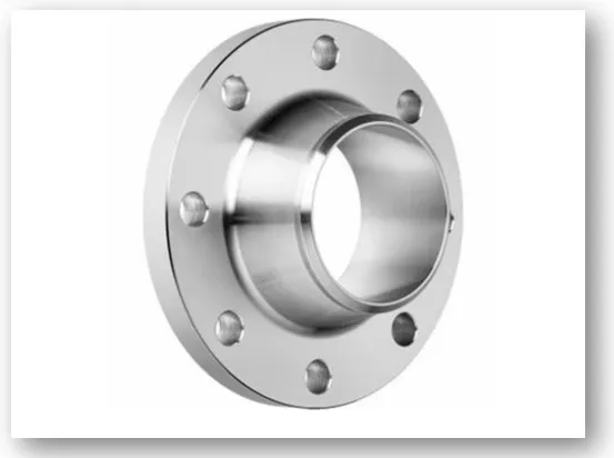
Lap joint flange
The lap joint flange consists of two components: a stub end welded to the pipe and a loose flange that slides over it, allowing rotation to facilitate alignment during assembly. Its design allows the use of more expensive materials in the stub end, while the loose flange can be manufactured in a more economical material.
Normally, the lap joint flange is used where frequent disassembly is necessary for cleaning, maintenance or repairs such as valves, pumps and filters. The cost of disassembly is reduced by the ease of rotating the flanges and aligning the bores. They are common in food and pharmaceutical industries, where flexible alignment and compatibility with corrosion resistant materials are necessary.
Technical characteristics
- Design standards: ASME B16.5 and ASME B31.3.
- Type of joint: Lap joint with short end and loose flange.
- Materials of construction: Available in various materials depending on the application.
- Face types: Raised (RF) and flat (FF).
- Pressure classes: 150, 300, 600, 600, 900, 1500 and 2500#.
- Nominal diameters (NPS): ½ to 24” and above.
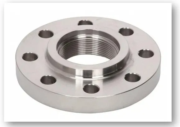
Threaded flange
The threaded flange uses an internal thread, usually NPT (National Pipe Thread), for direct connection to previously threaded pipes, eliminating the need for welding. They are ideal for locations where welding is not feasible, such as Ex-rated areas (explosive atmospheres), including gas stations and systems with flammable fluids.
Its use is not recommended in installations with large pressure and temperature variations, it is used in small diameters. They are common in temporary installations, water systems for domestic and industrial use and petrochemical products transportation. Due to the mechanical limitations of the thread, its pressure class is usually 300# or lower, although in some cases it can reach 600#.
Technical characteristics
- Design standards: ASME B16.5, B1.20.1, B31.3
- Type of union: Internal thread for connection with externally threaded pipes.
- Materials of construction: Available in various materials depending on the application.
- Face types: Raised (RF) and flat (FF).
- Pressure classes: 150, 300 and in limited cases up to 600#.
- Nominal diameters (NPS): ½“ to 2” maximum 4”.
Socket weld flange
The socket weld flange, specially designed for small diameters and high pressures, has an internal socket where the pipe is inserted, ensuring precise alignment before a fillet weld is made against the hub, providing a secure and leak resistant connection.
It is not used in critical services due to the difficulty in fully inspecting the integrity of the weld by non-destructive testing. In addition, a 1/16” gap must be left between the pipe and the bottom of the socket to allow for thermal expansion. It is common in hydraulic systems, steam lines and chemical processes.
Technical characteristics
- Design standards: ASME B16.5 and ASME B31.3.
- Type of joint: Internal socket for pipe insertion and external fillet weld.
- Materials of construction: Available in various materials depending on the application.
- Face types: Raised (RF) and flat (FF).
- Pressure classes: 150, 300 and 600#.
- Nominal diameters (NPS): ½ to 2“ maximum 4”.
Blind flange
The blind flange is a solid fitting without a central opening, used to seal pipe ends, valves or nozzles on pressurized vessels, used to isolate pipe sections during maintenance, pressure testing or future expansion, also used to block equipment and systems for operational safety.
Technical characteristics
- Design standards: ASME B16.5 and ASME B31.3.
- Type of joint: Bolted to the corresponding flange at the end of the pipe or equipment.
- Materials of construction: Available in various materials depending on the application.
- Face types: Raised (RF), flat (FF) and ring joint (RTJ).
- Pressure classes: 150, 300, 600, 600, 900, 1500 and 2500#.
- Nominal diameters (NPS): ½ to 24” and above.
Selection of industrial flanges
The correct choice of a flange depends on several fundamental factors:
- Operational variables: System pressure and temperature are critical, requiring the flange to withstand maximum conditions without failure; the type of fluid, corrosive or abrasive, demands resistant materials; and system service, continuous or cyclic, influences the selection of flange type and material.
- Flange type and material: The choice of flange type, such as weld neck or threaded, is based on specific needs, and the material, compatible with the fluid and the environment, varies from carbon steel to special alloys.
- Dimensions and pressure class: The nominal diameter (NPS) of the flange must match that of the pipe, and the pressure class must equal or exceed the maximum operating pressure of the system.
- Operating conditions: Environmental factors such as corrosiveness, abrasion and ambient temperature affect flange life, requiring materials resistant to specific conditions, such as salt water corrosion in marine environments.
- Manufacturing methods: The common methods, forging, machining and casting, are chosen according to the required mechanical properties and cost.
- Life cycle analysis and economic viability: The total cost of the flange is evaluated, from acquisition to replacement, seeking a balance between quality and cost, using inexpensive materials in non-critical applications and expensive alloys in demanding services.
- Regulations and standards: Compliance with regulations such as ASME and DIN is essential to ensure the quality and safety of the installation.
Why is maintenance of industrial flanges important?
Preventive maintenance of industrial flanges is required to avoid leaks, ensure safety and optimize system performance. This maintenance can be classified into:
- Visual inspection and NDT: Periodic inspections to detect corrosion or external damage.
- Condition-based maintenance: Vibration analysis to detect bolt loosening or infrared thermography to identify leaks or hot spots.
- Time-based maintenance: Replacing gaskets every certain period and retightening bolts according to an established schedule.
- Predictive maintenance: Vibration trend analysis, to predict when a bolt will loosen, and temperature trend analysis, to predict when a leak will occur.
Frequent performance of these activities depends on factors such as flange type, fluid, pressure, temperature and environment. It is advisable to follow the applicable regulations and the manufacturer’s recommendations. Although flanges are robust elements, preventive maintenance minimizes continuous interventions and reduces costs due to unplanned shutdowns.
Conclusions
Industrial flanges, in their various types, are strategic accessories in the interconnection of systems, guaranteeing a safe and efficient flow in various applications. From solid welded flanges to versatile threaded flanges, each type fulfills a specific function in the operation and maintenance of different industrial systems.
Proper selection, installation and maintenance of flanges, in compliance with technical standards, reduce the risk of leaks and failures, ensuring the mechanical integrity of the system. Standards such as ASME B16.5 establish precise specifications on dimensions, materials and tolerances, ensuring reliable performance. By optimizing the performance and protection of industrial assets, flanges are consolidated as fundamental elements for safety and operational efficiency in the industry.
References
- MARCEL; “Ring Type Joint Flanges Manufacturer” Consultado 10-03-2025; https://marcelforged.com/flange-types/ring-type-joint-flange-rtj-flange/
- ¿Cómo se lee la identificación de una brida?, Publicado en fecha 31-01-2018; https://valcoindustrial.com.mx/2018/01/31/como-se-lee-la-identificacion-de-una-brida/
- https://firstmold.com/es/tips/types-of-flanges/
- https://www.wermac.org/flanges/flanges_welding-neck_socket-weld_lap-joint_screwed_blind.html