Table of Contents
- What is thermal spraying?
- Different types of thermal spraying
- Thermal Barrier Coatings (TBC)
- Outdoor industrial infrastructure
- Inspection and acceptance
- Dry Film Thickness Measurement (DFT)
- Bond adhesion and strength
- Porosity assessment
- Typical failures: Causes, indicators, and solutions
- Surface engineering technologies
- Conclusions
- References
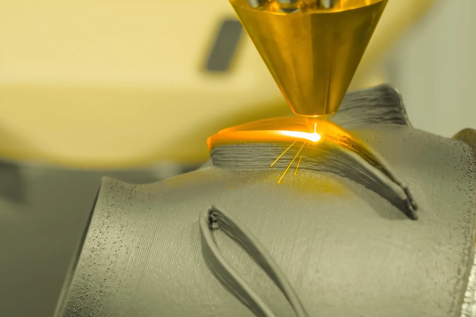
Thermal spraying is a versatile and widely used surface engineering technology that has found applications across various industries. It involves the deposition of materials onto a substrate to enhance its properties, such as wear resistance, corrosion resistance, and thermal insulation.
This technology uses a heat source to melt or soften the coating material, which is then sprayed onto the substrate surface in a finely atomized form. The most common heat sources include combustion flames, electric arcs, and plasma. The coating material may be in powder, wire, or rod form. Once the molten or softened particles strike the substrate, they rapidly solidify and form a thin coating layer. This process can be repeated multiple times to achieve the desired coating thickness.
What is thermal spraying?
Thermal spraying: Application, inspection, and typical failures is a group of industrial coating processes in which feedstock materials (metals, alloys, ceramics, cermets, or composites) are heated to a molten or semi-molten state and propelled at high velocity onto a prepared substrate. Upon impact, the droplets flatten, cool rapidly, and solidify into interlocking splats, forming a dense and adherent coating through successive torch passes.
The fundamental physics is based on two energy vectors acting simultaneously: thermal energy, which converts the feedstock into a molten or plasticized state, and kinetic energy, which propels the particles toward the substrate.
The balance between these two vectors, and the hardware used to generate them, is what differentiates each thermal spraying process from the others and ultimately determines the microstructure, porosity, bond strength, and performance of the resulting coating.
It deposits mechanically bonded coatings rather than metallurgically fused ones, meaning the substrate temperature remains low throughout the process (typically below 150–200 °C), preventing distortion or metallurgical damage to the base material.
Additionally, it can produce coatings from an almost unlimited range of materials, from sacrificial zinc for corrosion protection to yttria-stabilized zirconia for thermal insulation in gas turbines.
Different types of thermal spraying
Flame spraying (Wire/Powder Combustion)
Flame thermal spraying, the oldest and simplest form, uses an oxyacetylene or oxypropane flame to melt a wire or powder, which is subsequently atomized and propelled by a compressed air stream.
Particle velocities are relatively low (40–80 m/s), resulting in coatings with higher porosity and lower bond strength than more energetic processes.
Despite these limitations, flame spraying remains widely used for field repair of thermally sprayed zinc coatings on bridges and infrastructure, and for applying self-fluxing NiCrBSi alloys that are subsequently fused by torch or furnace heating.
Arc thermal spraying
Arc thermal spraying uses the electric arc generated between two consumable wire electrodes to melt the coating material. Compressed air (or an inert gas) atomizes the molten pool and propels it toward the substrate.
Because the energy source is electrical rather than combustion-based, arc spray systems are compact, economical to operate, and capable of achieving very high deposition rates, making them the preferred process for large-area anticorrosion applications such as steel bridges, offshore structures, and marine infrastructure.
The process is limited to electrically conductive wire feedstock; it cannot directly spray ceramics or cermets. Particle velocities of 80–150 m/s produce denser coatings than flame-sprayed equivalents, with typical porosity of 5–15%, depending on material and parameters.
High Velocity Oxy-Fuel (HVOF)
HVOF combines oxygen and a fuel gas (propane, propylene, hydrogen, or liquid kerosene) in a high-pressure combustion chamber. The expanding gases accelerate through a convergent-divergent nozzle to supersonic velocities, carrying powder feedstock to impact speeds of 300 to 600 m/s.
At these velocities, particles do not need to be fully molten; impact kinetic energy completes the bonding process. The result is an exceptionally dense coating (typical porosity 1–3%), very high bond strength (often exceeding 70 MPa), and low oxide content. HVOF is the benchmark process for demanding wear and corrosion applications.
Atmospheric Plasma Spraying (APS)
Plasma thermal spraying generates a high-enthalpy plasma jet by passing a gas (typically argon with hydrogen or helium addition) through a high-power DC electric arc between a tungsten cathode and a water-cooled copper anode.
The resulting plasma reaches temperatures above 15,000 K, sufficient to melt any known engineering material, including refractory ceramics and oxides. Powder feedstock is injected into the plasma jet, melted, and propelled onto the substrate at velocities of 200 to 600 m/s.
The main advantage of plasma spraying over HVOF is its unmatched thermal capability: it is the only process capable of depositing high-purity ceramics such as yttria-stabilized zirconia (YSZ), alumina (Al₂O₃), and titanium oxide (TiO₂). Table 1 provides a summary of the main types.
Table 1. Different Types of Thermal Spraying
| Process | Heat Source | Velocity (m/s) | Porosity (%) | Bond Strength | Typical Materials |
|---|---|---|---|---|---|
| Flame Spraying | Oxy-fuel combustion | 40–80 | 10–20 | Moderate (5–20 MPa) | Zn, Al, NiCrBSi, bronze |
| Arc Spraying | Electric arc | 80–150 | 5–15 | Good (10–35 MPa) | Zn, Al, ZnAl, stainless steel |
| HVOF | High-pressure oxy-fuel | 300–600 | 1–3 | Excellent (>70 MPa) | WC-Co, MCrAlY, cermets |
| Plasma Spraying (APS) | DC plasma arc (>15,000 K) | 200–600 | 5–15 | Good (20–50 MPa) | Ceramics (YSZ), MCrAlY, oxides |
Thermal Barrier Coatings (TBC)
Thermal barrier coatings represent the highest-performance application of thermal spraying technology.
Their function is to act as a thermal insulating layer between the hot combustion gas stream and the underlying metallic component, allowing turbine inlet temperatures to exceed the melting point of the nickel superalloy substrate or reducing cooling air requirements at the same temperature, thereby increasing turbine efficiency and component life.
Their function is twofold: to reduce the coefficient of thermal expansion (CTE) mismatch between the ceramic topcoat and the superalloy substrate, and to form a stable, slow-growing alumina layer (thermally grown oxide or TGO) that acts as a diffusion barrier at the ceramic-metal interface.
Outdoor industrial infrastructure
A broad category of outdoor industrial assets (petrochemical plant steel structures, power generation structures, chemical storage tanks, exposed pipelines, and transportation infrastructure) are protected using thermal spray coatings operating in corrosivity environments classified as C4 (high) to CX (extreme).
The main advantage over organic coating systems is long service life: a properly applied TSZ or TSA coating can outlast three or more full repainting cycles of conventional high-build epoxy systems, reducing total life-cycle maintenance burden and the safety and environmental risks associated with work at height or in confined spaces.
Inspection and acceptance
Inspection of thermal spray coatings is governed by ISO 2063 (Parts 1 and 2) for zinc and aluminum corrosion protection systems, supplemented by ASTM and EN standards for specific test methods.
Inspection is carried out in three stages: verification of surface preparation prior to application, monitoring during the spraying process, and post-application acceptance testing. Inspection parameters, applicable standards, instruments, and typical acceptance criteria are summarized in Table 2.
Table 2. Acceptance Criteria for Thermal Spray Coating Inspection
| Parameter | Method/Standard | Instrument | Typical Limit | Frequency |
|---|---|---|---|---|
| Dry Film Thickness (DFT) | ASTM D7091 / ISO 2063-2 | Magnetic/Eddy current gauge (e.g., PosiTector 6000) | As specified (e.g., ≥100 µm Zn) | Each layer, every 1–5 m² |
| Adhesion/Bond Strength | ASTM D4541 / ASTM C633 / ISO 4624 | Portable pull-off tester (dolly method) | Zn: ≥3.5 MPa; HVOF: ≥70 MPa | Test panels per batch + random checks |
| Porosity (%) | ASTM E2109 (lab) / visual field inspection | Optical microscopy/SEM; image analysis software | Arc spray: <15%; HVOF: <3% | Laboratory, on test coupons |
| Surface Profile (Rz) | ISO 8503 / ASTM D4417 | Replica tape (Testex) or needle profilometer | 50–75 µm (Zn/Arc); ≥75 µm (HVOF) | Before spraying, each blasting session |
| Visual Appearance | ISO 2063-2 / SSPC-VIS 1 | 10x illuminated magnifier; unaided vision | No cracking, blistering, bare areas, drips | 100% of coated area |
Dry Film Thickness Measurement (DFT)
Dry film thickness is measured non-destructively using electronic coating thickness gauges that operate on the principle of magnetic induction (for non-magnetic coatings on ferrous substrates, the most common case for TSZ and TSA on structural steel) or the eddy current principle (for coatings on non-ferrous substrates such as aluminum, or for stainless steel substrates).
ASTM D7091 establishes the practice governing these measurements, while the corresponding international standards are ISO 2178 (magnetic method) and ISO 2360 (eddy current method).
The SSPC-PA 2 standard prescribes a measurement frequency protocol: a minimum of five spot readings per measurement point, taken at a minimum separation of 25 mm; measurements are taken at intervals determined by the coated area (e.g., one reading per 10 m² for large areas). The average of the spot readings constitutes the thickness at that point. No individual reading may be less than 80% of the specified minimum.
Bond adhesion and strength
Adhesion tests for thermal spray coatings are inherently destructive and are therefore mainly performed on specific test plates that are sprayed during production (qualification test plates) or, statistically, directly on the coated surface at points designated in the inspection plan.
The pull-off method (dolly), regulated by ASTM D4541 and ISO 4624 standards, is the standard field method: a metal platform (usually 20 mm in diameter) is adhered to the surface of the coating with a high-strength epoxy adhesive, cured, and pulled perpendicular to the surface using a calibrated hydraulic or pneumatic tester.
For laboratory testing of thermal spray bond strength, ASTM C633 defines a tensile adhesion test using coupled loading fixtures attached to both sides of a sprayed disc.
This method is most commonly applied to HVOF and plasma spray coatings where high bond strengths (>10,000 psi/70 MPa) may exceed the capacity of the adhesive, resulting in a lower limit measurement rather than an actual failure load.
Porosity assessment
Porosity is an intrinsic characteristic of all thermal spray coatings, resulting from incomplete melting of the sprayed particles, gas trapped during particle flight, and the lamellar solidification mechanism.
The level of porosity depends on the process: flame-sprayed coatings can have a surface porosity of 10 to 20%; arc-sprayed metallic coatings typically have 5 to 15%; plasma-sprayed ceramic coatings have 8 to 15% (intentional in thermosetting coatings); and HVOF coatings have 1 to 3%. Porosity measurements are performed on metallographically prepared cross sections of production parts or complementary test coupons, following the procedures of ASTM E2109.
Typical failures: Causes, indicators, and solutions
Coating failures in thermal spraying can be classified according to their stage of origin: pre-application failures (surface preparation errors), application-stage defects (incorrect spray parameters), and in-service degradation (environmental and mechanical deterioration during service life).
Understanding the root cause of each failure mode is essential for both remediation and prevention of recurrence. Table 3 provides a structured summary of the most common failure modes.
Table 3. Most Common Coating Failure Modes
| Failure Mode | Main Causes | Visual Indicators | Correction |
|---|---|---|---|
| Delamination/Spalling | Inadequate surface preparation; contamination; CTE mismatch | Flaking, detached sections; hollow sound during tap test | Reblast to Sa 2½–Sa 3; remove all loose material; reapply |
| Excessive Porosity | Low particle velocity; excessive spray distance; moist feedstock | Sponge-like texture; rapid corrosion in service; visible voids under microscope | Optimize spray parameters; apply sealant; check feedstock moisture |
| Thermal Cracking/Mud Cracking | Substrate overheating; excessive DFT per pass; rapid cooling | Surface crack network resembling dried mud | Control substrate preheat; reduce pass thickness; allow controlled cooling |
| Bond Coat Oxidation (TBC) | High-temperature service; oxygen penetration through porous topcoat | TGO growth; loss of adhesion; ceramic spallation | Use low-porosity HVOF bond coat; optimize MCrAlY composition; monitor TGO thickness |
| Blistering/Corrosion | Pores/voids; soluble salt contamination; insufficient sealing | Dome-shaped blisters; rust staining at edges; flaking sealant | Enforce chloride limits (≤20 mg/m²); reblast; seal immediately after spraying |
| Low Adhesion at Application | Surface contamination (oil, rust, condensation); incorrect grit profile | Pull-off values below specification; edge lifting | Verify dew point margin (≥3 °C); reclean surface; confirm angular profile ≥50 µm |
Surface engineering technologies
Thermal spray coatings represent one of the most versatile and durable surface engineering technologies available to corrosion protection and structural maintenance engineers.
The performance of any coating system applied by this method is inseparable from the quality of surface preparation, applicator competence, and the rigor of the inspection and acceptance regime applied throughout the process.
ISO 2063 provides the fundamental regulatory framework for corrosion protection applications; the supporting ASTM test standards (D7091, D4541, C633, and E2109) provide the specific quantitative tools to verify compliance.
In the infrastructure sector, decades of documented field performance — including duplex TSZ-coated bridges in service for more than 50 years in corrosive coastal environments — confirm that thermal spray metallization provides the longest uninterrupted service life of any steel corrosion protection system currently available.
The main barriers to broader adoption are not technical but operational: the requirement for abrasive blasting to Sa 2½–Sa 3 (often challenging in populated or environmentally sensitive areas), operator training and qualification, and the higher initial application cost compared to conventional painting — an investment typically recovered within one or two maintenance cycles over the asset’s lifetime.
Conclusions
Thermal spraying stands as one of the most robust and versatile technologies in modern surface engineering, delivering high-performance solutions against wear, corrosion, and extreme thermal conditions. Its success depends not only on the selected process — flame, arc, HVOF, or plasma — but on comprehensive control of operational variables, proper surface preparation, and strict compliance with inspection standards.
When applied under rigorous technical standards, thermal spraying significantly extends asset service life while reducing life-cycle costs and operational risks associated with frequent maintenance. Its strategic adoption in critical infrastructure and high-performance components represents a technically justified and sustainably cost-effective long-term investment.
References
- https://www.iso.org/standard/76499.html
- https://store.astm.org/d4541-22.html