Author: Ing. Carlos Álvarez, October 24, 2023.
Introduction
In the world of industrial inspection, the constant search for innovative technologies that allow a more precise and efficient evaluation of materials and products is a priority. In this context, Phase Coherence Imaging (PCI) has emerged as a promising technique for a variety of applications, both in technical and medical fields.
This technique is relatively new within the ultrasonic testing method that complements the TFM and addresses some of its limitations, it is an addition to the phased array ultrasound technique (PAUT). It is based on the concept of preserving and using the phase information of received ultrasonic signals. By doing so, you can provide valuable information about the structure being inspected.
In this article, we will explore a particularly promising variant of PCI, the ultrasonic Phase Coherence Imaging technique, and its potential in the field of evaluation.
Principle of Phase Coherence Imaging technique
First, the acquired A-scans are normalized, that is, the differences in delay and amplitude of the A-Scans are adjusted or corrected, and then the phase distribution of the different A-scans is compared for each position in the TFM zone. For a given position, the higher the level of coherence between A-scans, the stronger the signal response will be for that position (with a maximum of 100%).
That is, the intensity of the signal is a function of the level of coherence, which, as explained, refers to the measure of similarity or agreement between the waveforms (phase) recorded in the records of the different A-Scan data. . In this way, the processing of the received signals through PCI is based exclusively on the phase information carried by the elementary A-scans in order to generate a TFM representation and is independent of the amplitude of the signals.
Discontinuities better detected by PCI
Omnidirectional sources, such as porosities, tip diffractions, and slag, tend to show high intensity as they are viewed with approximately the same phase by many Full Matrix Capture (FMC) emitter-receiver pairs. Reflectors whose phase has a strong directional dependence, such as front surface, back wall, delaminations, lack of fusion (LOF), etc., produce low value PCI, facilitating the detection of volumetric defects (porosities and slag) and the identification of diffracted signals at the crack tip for better sizing.
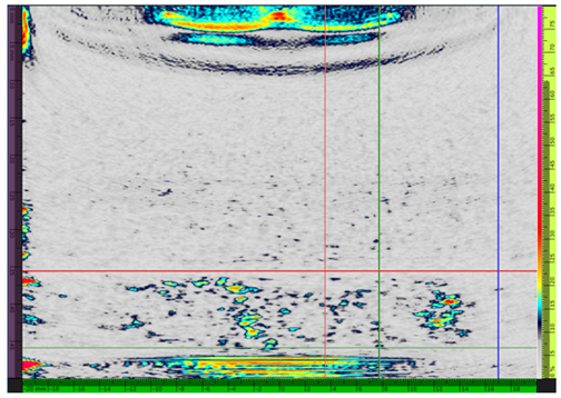
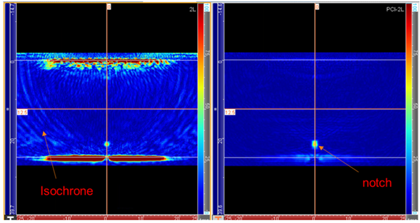
In Figure 1, you can see the difference between the TFM and PCI images when using a probe with normal incidence. In the TFM image you can see the indications of the entrance surface, background and lateral artifacts or noise. These indications are suppressed in the PCI image because the signals that cause them are incoherent, so a cleaner image is obtained; which allows small faults to be detected in the absence of noise in the volume of the component and near the input surface.
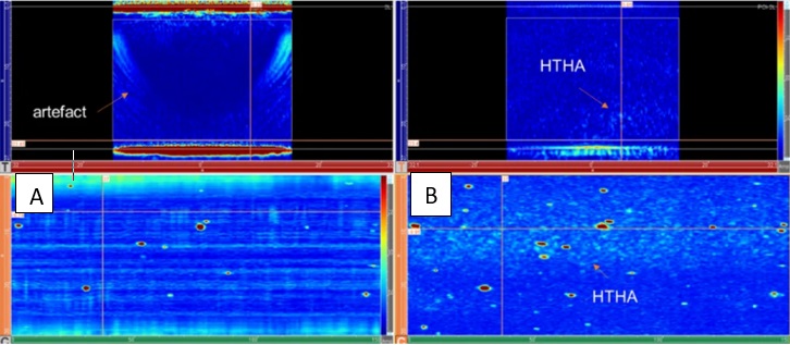
By suppressing the incoherent noise of the grain size by applying PCI, the detection and evaluation of the hydrogen attack phenomenon at high HTHA temperatures is greatly facilitated (see Figure 2), making this technique ideal in the inspection of components with a probability of incipient gestation of this type of material degradation.
Detección de daños por Sulfuro de Hidrógeno (H2S) húmedo: Aunque también puede ser detectado mediante TFM, es difícil determinar mediante esta técnica si este tipo de discontinuidad se conecta con la superficie. Mediante PCI esto es fácil de determinar por la coherencia de las señales típicas (ver figura 3).
Applications of the Phase Coherence Imaging technique
The Phase Coherence Imaging technique overcomes some of the limitations of the Total Focusing Method (TFM), based on this it is applied in the same work areas for the following specific tasks:
- Detection of High Temperature Hydrogen Attack (HTHA): The coherent signals produced by intergranular microcracking by HTHA make PCI the best option for this type of evaluations.
- Detection of damage by wet Hydrogen Sulfide (H 2 S): Using this technique it is easy to determine due to the coherence of the typical signals.
- Monitoring of cracks in service: The high repeatability of the results is ideal for monitoring cracks during the service of the component (pipes, equipment, etc.) when applying methodologies such as attitude for service or Fitness For Service (FFS).
- Weld evaluation: It combines the advantages of reflections from small discontinuities with diffractions (such as TOFD), and also requires fewer groups compared to PAUT/TFM for the same coverage.
Advantages of the Phase Coherence Imaging technique
- Inspection of highly attenuating coarse-grained materials: Since the intensity of the indication is a function of the level of coherence and not the amplitude, and the signals or noise typical of these materials are incoherent, it is suppressed from the screen, so small flaws can be detected in these materials.
- Detection of small faults near large reflectors: When suppressed, the indication of large areas, such as the input surface, which produces an incoherent signal, is also suppressed, allowing discontinuities to be detected near it (higher input resolution ).
- High repeatability; which makes it appropriate for monitoring cracks in service.
Disadvantages of the Phase Coherence Imaging technique
- High initial cost due to the complexity of the algorithm program additional to the TFM.
- Lower acquisition speed due to high data processing, which reduces field service production.
- It does not require manipulating the gain because it is based on the coherence and not the amplitude of the signals.
- Requires fewer groups to cover the same volume of material (for example: a weld)
Bibliographic references
FREDÉDÉRIC REVERDY. The Pros and Cons of Phase Coherence Imaging (PCI); Consulted on October 21, 2023; https://blog.eddyfi.com/en/the-pros-and-cons-of-phase-coherence-imaging-pci
EVIDENT. Phase Coherence Imaging (PCI). Better practices; Consulted on October 22, 2023; file:///C:/Users/INSTRUC/Downloads/PCI_Getting_Started_Guide_final.pdf
TREVOR TARTAGLIA. Is Phase Coherence Imaging Right for Your Application?; Consulted on October 23, 2023; https://blog.asnt.org/is-phase-coherence-imaging-right-for-your-application/