Introduction
Carbon steel storage tanks are important structures or containers for the operation and production processes of plants in the oil, gas and petrochemical areas; in which the products that feed and process the industrial plants are stored, such as: drinking water, industrial water, waste, additives, finished or semi-finished products, among others. which are basic for the production and operation processes, hence the importance of these assets for the storage of these products.
When hazardous substances are stored in storage tanks, reducing the risk of leaks is crucial. Corrosion in storage tanks can cause significant product leaks and therefore environmental contamination. Due to these types of problems, it is necessary to guarantee the safety and reliability of these assets.
These containers are structurally made up of the roof, wall and floor. Of these three parts, the floor is the most difficult section to inspect, detect and control corrosion, this is mainly due to the difficulty of accessing this part.
Corrosion on tank floors
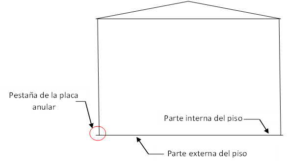
Tank floor corrosion occurs in three different environments. In the internal part where it is in contact with the stored product (gasoline, naphtha, fuel oil, oil, drinking water, oil, etc.), in the external part in contact with the ground and in the flange of the plate or annular plate where it is exposed to the atmosphere and the ground (figure 1).

Next, an analysis of these three environments is carried out.
Internal part : To evaluate the corrosivity in the internal part of the tank floors, it is important to determine the type or characteristics of the stored product, temperature, chemical aggressiveness, pH, sulfur content, amount of salt water and sludge drag, among others.
After evaluating how corrosive the product can be on the flooring material, it is defined whether protection against corrosion is required or not. In case of needing protection, the most used and very effective method is to avoid contact between the product and the substrate; for which, the most suitable industrial paints or coatings are applied for each case.
Some products, like oils, are not corrosive; therefore, the application of coating on the floor is not necessary, but it should be considered in the evaluation, if there is the possibility of corrosive solid entrainments in the fluid.
As a corrosion preventive activity, the tanks that contain salty water in the product (eg crude oil) must be drained frequently to remove the water that settles at the bottom.
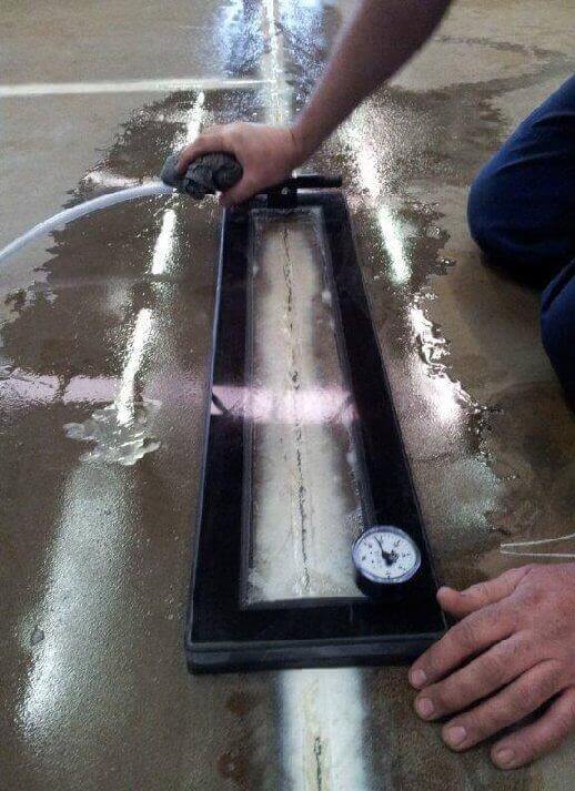
To detect corrosion or flaws in the internal part of the floor; First, a thorough visual inspection (VT) must be carried out on all plates, welds, collectors, reinforcements and coatings. The result of this evaluation will determine if it is necessary to use another Non-Destructive Testing (NDT) method; such as Penetrating Dyes (PT) or Magnetic Particles (MT), to reveal surface or sub-surface cracks in welds, vacuum box leak tests can also be used to rule out or detect through cracks in welds (figure 2), [ 1 ] . Obviously all the inspections or NDT mentioned above, require that the tank is out of service, clean and degassed.

Figure 2. Photographic representation of a vacuum box [ 1 ] .
External part: The external part of the floor is the area that is in contact with the ground and to determine the corrosiveness of this environment, a complete analysis of the soil must be carried out, in order to define the type of soil, pH, humidity, temperature, chemical composition and soil resistivity, among others. These analyzes must be carried out by expert corrosion personnel who will determine the resistivity of the soil, acidity, redox potential, if the water content favors electrochemical corrosion, the presence of sulfides, sulfates, chlorides and organic elements, among others, to establish them. adequate corrosion controls.
Corrosion prevention measures.
After evaluating all these factors and defining the corrosion mechanisms that may be generated, the following corrosion prevention measure is taken:
- Design and build the foundation or foundation with suitable materials and free of moisture. The selection of materials to install must be of low corrosivity and place them in a layered arrangement as follows: Excavate and remove the natural soil from the ground, replace it with a first layer of compacted sifted sweet sand and on top of it an asphalt layer also compacted . Under these two layers, a non-biodegradable waterproof geotextile mesh must be placed, which prevents the entry of rainwater or water from the groundwater level.
- Another type of foundation to install can be concrete; which must be manufactured using sifted sweet sand
- Foundation designs must be made with slopes that keep the cementation concave. To prevent rain from entering under the floor.
- For those cases where the soil resistivity is very low (< 10 Ωm) where the degree of aggressiveness is severe or when the resistivity is between 10 Ωm – 100 Ωm, whose aggressiveness is moderate, cathodic protection should be installed, preferably by impressed current [ 2 ] .
Monitoring techniques.
To detect corrosion or faults in the external part of the floor, and considering that this area is not accessible, NDT methods are used that allow the evaluation of conditions from the internal part.
Magnetic Flux Leakage (MFL): The most used and reliable technique for this case is the Magnetic Flux Leakage (MFL, or Magnetic Flux Leakage). With these techniques for ferromagnetic materials, the volumetric losses in the plates are detected, temporarily magnetizing the component to be tested, to then locate the distortions in the magnetic flux that occur in internally and/or externally corroded areas. The equipment used for the test can scan more than 90% of the bottom surface of the tank (figure 3)[3], and the results of the evaluation are presented by software, on a map with a variation of colors that define the critical zones, (figure 4) [4].

This inspection technique is complemented by the ultrasound NDT inspection method, with which the remaining thickness is determined; This MFL technique detects volumetric losses, not thicknesses. Likewise, the ultrasound equipment is used to evaluate areas where it is not possible to access with the MFL equipment, such as the collecting pots.

The flange of the annular plate or plate: This zone considered as the critical zone of the storage tanks, is made up of a welded joint, a section of the annular plate and the lower part of the wall (See figure 5) is of great importance and of special attention due to its configuration and location. , is where the greatest pressures and stresses are exerted on the storage tank and where failures with catastrophic consequences can occur. This area is exposed to two following environments.
- The lower part that is in contact with the ground: This area is evaluated and controlled for corrosion in the same way as the external part of the floor.
- The upper part that is exposed to the atmosphere: To determine the corrosivity in this area, several factors must be evaluated, humidity, considering that the critical value is above 70%, rainwater, the saline environment and the elements or component generated by nearby industrial facilities.
Finally, the factors that intervene in the corrosion of steel in this area are air and humidity, aggravated by the presence of diluted acids and saline solutions.

As this area is easily accessible, it is evaluated with the tanks in operation, mainly through the NDT Direct Visual Inspection (VT) technique, to locate flaws in the coating and corrosion on the flange on the external side of the tank.
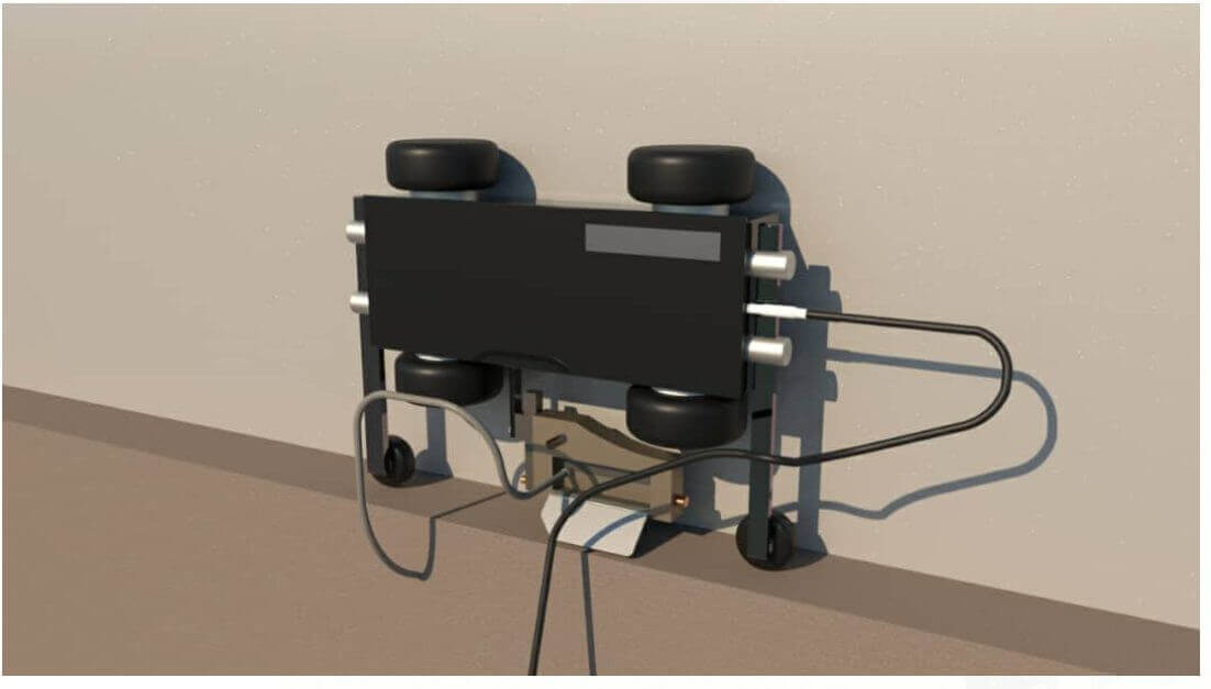
Guided Waves: To inspect the critical area in contact with the ground, equipment such as the one shown in Figure 6 [ 5 ] has been developed. that use the ultrasound test through the qualitative technique of Guided Waves to locate damages in the critical zone. The aforementioned technique is based on the concept of guided laminar wave impulses that propagate from the transducer towards the annular plate and when there is corrosion, the ultrasonic waves return to the transducer, converting the signal and indicating the discontinuity. See figures 7


Liquid Penetrants : When liquid penetrant testing is specified, it shall be in accordance with Section V, Article 6 of the ASME Code. The liquid penetrant examination method is an effective means of detecting discontinuities that are open to the surface of nonporous metals and other materials. Typical discontinuities detectable by this method are cracks, joints, laps, cold seams, laminations, and porosity.
Acoustic Emission (EA). To finish, we will mention the Acoustic Emission (EA) NDT technique, which is used to carry out the comprehensive evaluation of storage tanks. This technique can be defined in a simple way as an audible sound test that detects the sound emitted by materials when they are subjected to stress or pressure.
The basic principle of EA techniques is based on the fact that materials emit sound at their weakest points (cracks, pores, loss of thickness, among others), when subjected to loads. In general, it does not measure the size of the defects, but it locates the points with potential damage, which must be evaluated with other NDT techniques (generally ultrasound) to quantify it.
The main importance of this technique is that it is carried out with the tanks in service, it tests the entire structure of the tank at once, it detects a leak at the bottom that would affect the water table, it is relatively inexpensive and it is a great support for the expansion of the risk-based inspection (RBI) methodology.
Bibliographic references:
[ 1 ] Industrial Testing & Inspection Services (ITIS); itis-nl.com.
[ 2 ] Student publications ; aiu.edu
[ 3 ] Eddyfi Technologies; https://www.eddyfi.com/en/product/floormapx-mfl-tank-bottom-inspection .
[ 4 ] Eddyfi Technologies FloormapX System; https://www.eddyfi.com/en/product/floormapx-mfl-tank-bottom-inspection.
[ 5 ] Taken from the ESCON Group of Companies http://www.escon-dt.com/assetmanagement.php .

About the Author.
An engineer. Euclides Quinonez. Senior inspector, equipment mechanical integrity and asset reliability analyst, plant shutdown technical manager, feasibility evaluator of investment projects with 40 years of experience in the oil, petrochemical and gas industries.

