
Introduction
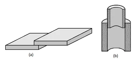
A lap joint is a geometric configuration widely used in industry for manufacturing and equipment repair processes. This method consists of overlapping one plate over another in parallel, allowing the creation of strong and durable joints through the application of fillet welds or other types of welds. This technical article explores the basics of lap welding, describing its techniques, characteristics and the most common applications in various industries.
What is lap welding?
Although the designation overlap is determined by the overlapping joint, in practice it is common to mention the term lap weld, lap weld or lap weld, which is nothing more than a fillet weld or other type of weld applied to these joints. In general, the term lap welding refers to the configuration of overlapping metal parts that are joined by a welding process.
The welding process in an overlapping configuration involves the fusion of the overlapping edges of the metal parts, creating a strong and durable weld. This joint, depending on the project, can be welded on one or both overlapping edges, with the understanding that welding both edges involves doubling the amount of welding and considerably increasing costs.
Lap welding processes
It can be performed using several methods, each with its own advantages and disadvantages. The most common method is electric arc welding which includes coated electrode arc welding or SMAW, MIG/MAG welding, TIG welding, submerged arc welding or SAW, and the resistance method. These methods are partially described below:
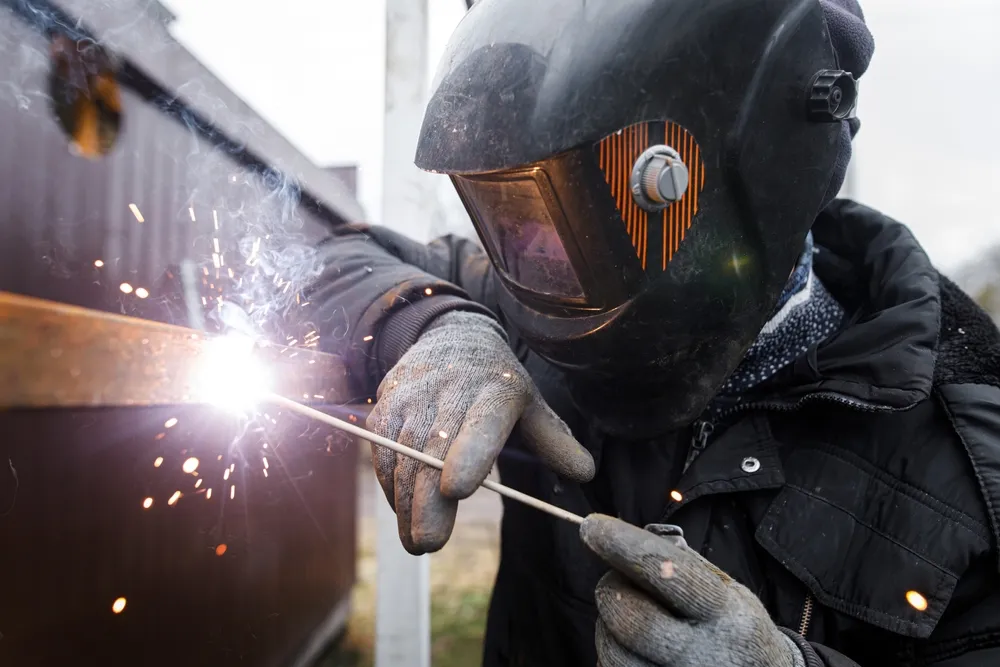
SMAW welding (Shielded Metal Arc Welding)
It is a manual process, where the electric arc is established between a consumable coated electrode and the metal parts to be joined, generating the heat necessary to melt the metal and the flux coating of the electrode, the melting of the latter forms a gas that protects the arc from the atmosphere. This process is versatile and can be used on a variety of materials and thicknesses.
GMAW welding (Gas Metal Arc Welding)
Also known as MIG (Metal Inert Gas) / MAG (Metal Active Gas), it uses a gas to shield the arc from the atmosphere. This method is popular for its high deposition rate and its ability to produce clean, high quality welds. This method is popular for overlap welds in the manufacture of industrial machinery and equipment, where thick, high performance metal parts are required to be joined.
GTAW welding (Gas Tungsten Arc Welding)
GTAW or TIG (Tungsten Inert Gas) welding uses a non-consumable tungsten electrode and an inert gas to shield the weld. This method is known for its precision and is ideal for high quality welds on thin materials.
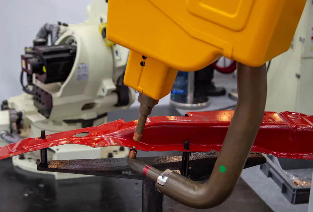
RW Welding (Resistance Welding)
It is a method where overlapping metal parts are joined together, without material input, by applying pressure and heat generated by an electric current. This method is common in the manufacture of high production products, such as in the automotive industry and household appliances where most of them are robotized systems.
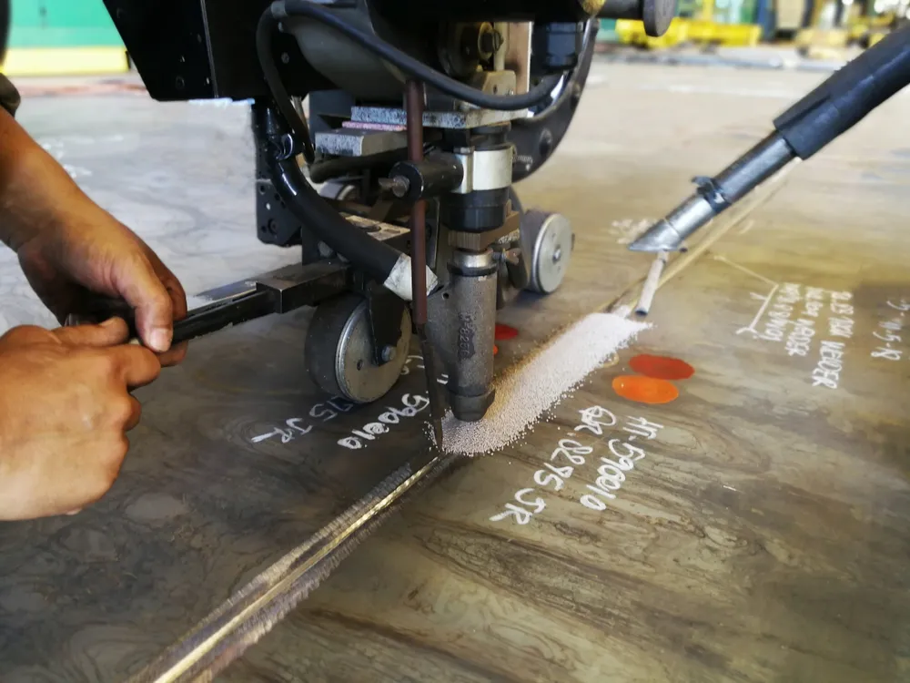
SAW welding (Submerged Arc Welding)
Submerged Arc Welding or SAW is an automated horizontal flat position welding process from above (1G/1F) that uses an electric arc maintained between a continuous wire electrode and the work piece. The arc is “submerged” under a blanket of granular flux, which protects the molten metal from atmospheric contamination and improves weld quality.
It is known for its high deposition rate and deep penetration in a controlled environment, which makes it ideal for high production applications. It is typically used in the fabrication of heavy structures such as beams and columns in construction, as well as in the fabrication of storage tank floors and roofs, and industrial machinery components, where process automation reduces welding time and improves joint efficiency and uniformity.
Lap welding techniques
Lap welding techniques vary depending on the welding method used and the specific characteristics of the project. Some of the more common techniques include:
Fillet welding
It is the most common in this type of joint, where the weld is deposited at the intersection of the two overlapping pieces, forming a triangular bead. These welds are strong and versatile, and can be made in a variety of positions, including horizontal, vertical and overhead.
Spot welding
This technique is mainly used in resistance welding. In spot welding on thin sheet metal, pressure and electric current are applied at specific points of the overlapped joint, forming spot welds. It is common in the manufacture of automobile bodies and household appliances.
Plug welding
Plug welding involves creating holes in overlapping metal parts and then welding through these holes, joining the parts together. This technique is useful when a strong joint is required, but it is desired to maintain the surface appearance without visible beads.
Defects in lap welding and how to prevent them
As with any welding process, lap welding can have defects that affect the quality and integrity of the joint. Some of the more common defects include:
- Porosity: Occurs when gas bubbles are trapped in the molten metal, forming cavities in the weld. This can weaken the joint and make it susceptible to fracture. To minimize this defect, it is necessary to ensure cleanliness, control feed rate, use of the proper shielding gas, proper selection and storage of electrodes and avoid the entry of external air flow during the welding process.
- Slag inclusions: Occur when non-metallic materials are trapped in the weld. To avoid this, good cleaning between passes is required, using the appropriate current and voltage levels to avoid excessive slag formation, as well as using electrodes and filler materials that minimize slag formation.
- Cracks: These can form due to shrinkage of the molten metal during cooling. They can be superficial or internal and are a critical defect that can compromise the integrity of the joint. These discontinuities are avoided by preheating the base parts when necessary, controlling the temperature between passes, avoiding too rapid cooling and using thermally and mechanically compatible materials.
- Poor penetration: Occurs when the filler metal does not adequately penetrate the base parts, resulting in a weak joint. This can be caused by incorrect welding parameters or improper part preparation. Avoiding these failures requires using the correct current, voltage and feed rate and using the correct electrode angle and direction of feed.
Design of fillet welds for lap joints
Proper design of a fillet joint ensures strength and durability by considering the following:
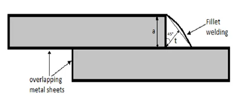
- Fillet height (a): It is the length of the leg or leg of the isosceles right triangle that forms the weld. In the case of fillet welds in overlap joints, this height is determined by the thickness of the plate on the edge of which the weld is applied.
- Effective throat (t): The distance from the root of the weld to the fillet face, forming a 45° angle with the leg or leg of the triangle, as shown in figure 5.
- Load distribution: Design the welded joint so that loads are evenly distributed.
Fillet welding Inspection
To evaluate the quality of fillet welds, several Nondestructive Inspection (NDT) methods can be applied such as Visual Inspection (VT) to detect surface defects, Liquid Penetrant (LP) to detect surface cracks and Magnetic Particles (MT) to detect surface and subsurface discontinuities in ferromagnetic materials.
More advanced NDT methods such as Ultrasound (UT) and Industrial Radiography (RT) can be used, but are limited for evaluating fillet welds due to their complex geometry and acute angles, which makes interpretation of ultrasonic signals difficult. Multiple reflective surface geometries can generate multiple echoes and false positives. For radiographs, the configuration of overlapping parts and the difficulty of proper placement of the radiation source make it difficult to obtain clear and detailed images.
Conclusions
Lap welding is an important and commonly used process in the fabrication and repair of metal structures, storage tanks and general equipment. Its ability to create very strong and durable joints makes it ideal for a variety of industrial applications. Lap welding techniques offer flexible solutions for different design and production requirements.
It is essential to understand the potential defects in lap welding to ensure the quality of the joints. With proper knowledge and application of correct techniques, lap welding will continue to be a valuable tool in modern engineering and manufacturing.
References
Own source