
Table of Contents
- What is a hydraulic turbine?
- Theoretical foundations of hydraulic turbines
- Hydrodynamic fundamentals of hydraulic turbines
- How does conservation of mass apply to a hydraulic turbine?
- How a hydro turbine in a hydroelectric power plant works
- Types and configurations of hydraulic turbines
- Technological innovations in water turbine applications
- New technologies in hydraulic turbines
- Conclusions
- References
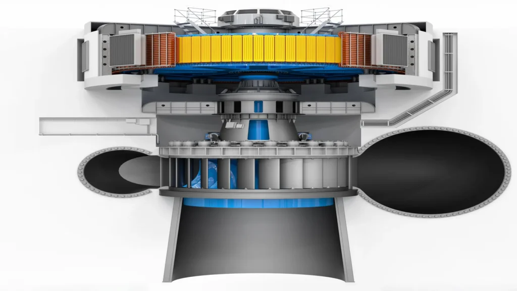
Hydraulic turbines constitute the technological core of hydroelectric generation, representing a strategic and highly efficient methodology for the conversion of potential and kinetic energy of water into rotational mechanical energy and subsequently into electrical energy. The function of this hydraulic equipment is to transform the kinetic energy of water into mechanical energy. It is an essential rotating machine of hydroelectric power plants and shows a high efficiency: it is estimated that turbines are capable of converting more than 90% of the kinetic energy of the water they capture into mechanical energy.
A hydraulic turbine consists of a fixed part, called the stator, and the wheel or rotor. The former directs and regulates the flow of water, and the latter transfers the kinetic energy of the water to the shaft on which it is mounted. This technical article discusses the fundamental principles that govern the operation of these machines, examines the distinctive configurations and geometries of the main types, analyzes the critical operational parameters. It also explores the contemporary technological advances that are redefining their capabilities and fields of application.
What is a hydraulic turbine?
A hydraulic turbine is a machine that transforms the energy of a fluid (kinetic and potential energy), usually water, into mechanical rotational energy. This energy can be potential or kinetic.
Theoretical foundations of hydraulic turbines
Hydraulic turbines operate under the principles of fluid mechanics and conservation of energy, especially the potential and kinetic energy of water. When water is at a certain height (as in a reservoir or dam), it possesses gravitational potential energy. By allowing it to flow to a lower level, this energy is transformed into kinetic energy, which can be harnessed by a turbine to generate rotational motion.
Bernoulli’s theorem is one of the most relevant theoretical bases, since it describes how the pressure, velocity, and height of a fluid are interrelated. Likewise, Newton’s second law explains how the change in the amount of fluid motion produces a force that drives the turbine blades. In addition, hydraulic design principles are applied, such as flow optimization, minimization of frictional losses and selection of the turbine type according to the water head and available flow.
Hydrodynamic fundamentals of hydraulic turbines
Hydraulic turbines are governed by hydrodynamic principles that explain how the energy of moving water can be captured and transformed into mechanical energy. They harness two main forms of fluid energy: kinetic energy, associated with the velocity of the water, and potential energy, related to the head or pressure of the flow.
The behavior of water inside a turbine is described by the laws of fluid dynamics, in particular, Euler’s equation for turbomachines and the theorem of conservation of the quantity of motion. These principles make it possible to calculate the forces acting on the runner blades as the flow passes through them. Aspects such as relative fluid velocity, circulation, and hydrodynamic profiles that maximize system performance are also considered.
In addition, phenomena such as cavitation, vortex formation and hydraulic losses, which directly influence the efficiency and durability of the turbine, are taken into account. A proper hydrodynamic design allows optimizing the energy transfer from the fluid to the rotor, minimizing these undesired effects.
The Euler equation for turbomachines
The Euler equation for turbomachines is a fundamental principle in the energy analysis of devices that exchange energy with a fluid, such as hydraulic turbines. This equation establishes the relationship between the mechanical work exchanged per unit mass and the change in angular momentum of the fluid as it passes through the turbine runner.
In general form, the equation is expressed as:
ΔW=u2cu2-u1cu1
where:
- ΔW, is the specific work transmitted to the shaft.
- u, is the peripheral velocity of the impeller.
- cu, is the tangential component of the absolute velocity of the fluid.
- subscripts 1 and 2 indicate the impeller inlet and outlet, respectively.
This equation reflects how the interaction between the fluid and the turbine blades depends on the relative and absolute velocities of the flow. The value of ΔW determines the power that the fluid transfers to the rotor. In an efficient hydraulic turbine, the geometric design of the blades is optimized to maximize this work.
Theorem of conservation of the quantity of motion
The theorem of conservation of the quantity of motion, applied to a fixed control volume, states that the net force exerted on a fluid is equal to the variation of the flow of quantity of motion through that volume. In hydraulic turbines, this principle allows calculation of the forces exerted by the flow on the blades and vice versa.
In its scalar form for one-dimensional flow, it is expressed as:
F=ṁ(vexit−vinlet)
where:
- F, is the net force exerted.
- ṁ,˙ is the mass flow rate of the fluid.
- v, represents the flow velocity at the inlet and outlet points.
When applied to turbines, the direction and magnitude of the velocities are taken into account, which allows to obtain not only the net force, but also its useful component (usually tangential) that produces the rotation of the runner. The theorem also makes it possible to analyze effects such as the change of direction of the water jet, the efficiency of the impulse, and the available hydraulic load.
Taken together, these two principles – Euler and conservation of quantity of water – are the basis of the theorem.
How does conservation of mass apply to a hydraulic turbine?
Conservation of mass states that, for steady-state, stationary flow, the mass of fluid entering a turbine must be equal to the mass leaving (assuming no mass accumulation within the system). In general form:
ṁinlet=ṁoutlet
Where: ṁ,˙ is the mass flow rate, and is defined as ρ⋅Q, where ρ is the density of the fluid and Q is the volumetric flow rate.
This implies that, under normal operating conditions, water does not compress or expand significantly (being an incompressible fluid such as water), so the volume entering and leaving also tend to be equal. This principle allows the proper design and sizing of the system components: nozzles, distributors, impellers and outlet ducts, so that there are no obstructions, overpressure or excessive losses.
The behavior of hydraulic turbines is based on the principles of conservation of mass, momentum and energy, expressed by means of the Euler equations for turbomachines. The fundamental equation that describes the behavior of a turbomachine under the one-dimensional flow approximation is called the Euler equation.
Specifically, the angular momentum transferred between the fluid and the rotor can be expressed as:
M=ρQ(r2vu2-r1vu1)
Where:
- M, is the moment or torque exerted by the fluid on the impeller.
- ρ, is the density of the fluid.
- Q, is the volumetric flow rate.
- r1,r2, are the radii of the impeller at the fluid inlet and outlet.
- vu1,vu2, are the tangential components of the absolute velocity of the fluid at the inlet and outlet, respectively.
How a hydro turbine in a hydroelectric power plant works
A hydro turbine in a power plant works by harnessing the potential energy of water stored in a dam. Water released from a reservoir flows at high velocity to the turbine blades through a conduit known as a pressure channel or adduction tunnel. The force of the moving water rotates the turbine blades, which converts the kinetic energy of the water into mechanical energy. This process occurs in a controlled manner to maximize the efficiency of the energy conversion.
The turbine shaft, which is connected to a generator, rotates as the blades move. This shaft rotation is used to generate electricity, using the principle of electromagnetic induction. In the generator, the movement of the rotor within a magnetic field produces an electric current. The power generated is then sent through transmission lines for distribution. Thus, hydro turbines play a fundamental role in the generation of clean and renewable energy in hydroelectric power plants.
The following video is an animation showing how hydro turbines in a power plant convert water energy into mechanical energy. Source: Tennessee Valley Authority.

How does a hydraulic turbine work in a hydroelectric power plant?
Types and configurations of hydraulic turbines
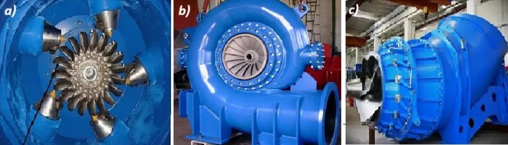
Turbine types include action turbines and reaction turbines. The classification of hydraulic turbines is based on the physical principle that describes how the fluid (water) interacts with the turbine blades to generate motion; this distinction is related to how the energy from the water is transferred to the turbine. They are categorized into two types, by Action and by Reaction. The following image shows the most commonly used types of turbines: Pelton, Francis and Kaplan.
The following are described according to the type of configuration:
Action turbines
Pelton turbine
The Pelton wheel is a hydraulic impulse turbine created by the American inventor Lester Allan Pelton in the 1870s. This wheel extracts energy from the momentum of moving water, as opposed to the dead weight of water, like the traditional supercharging water wheel.
The water leaving these wheels used to maintain a high velocity, which absorbed much of the dynamic energy reaching the wheels. The geometry of the Pelton vanes was designed so that when the rim was rotating at half the speed of the water jet, the water exited the wheel with very little velocity; therefore, its design extracted almost all of the impulse energy from the water, making it a very efficient turbine.
Turgo turbine
This turbine is defined as an action turbine, axial flow and partial admission, whose most important elements forming the turbine are the distributor or injector and the runner.
Variant of the impulse turbines with the following distinctive characteristics:
- Jet impingement at an angle (typically 20°) to the impeller plane.
- Higher flow capacity compared to Pelton for the same diameter.
- Specific velocity between 20 and 50 m-kW.
- Lower susceptibility to ventilation losses.
Michell-Banki (Crossflow) turbine
Michell-Banki turbines, also known as cross-flow turbines, are hydraulic machines used for power generation in small-scale hydroelectric projects. Since its inception, the Michell-Banki turbine has been the subject of multiple research focused on improving efficiency in order to obtain maximum utilization of the available hydraulic resource.
Technical characteristics:
- Radial flow with double passage through the vane crown.
- Hydrodynamic profile defined by dimensionless coordinates based on impeller radius.
- Optimal 0.66” outside/inside diameter ratio.
Reaction turbines
Francis turbine
The Francis turbine is a reaction turbine that operates on the principle of converting the kinetic energy of water into mechanical energy through a combination of radial and axial flow.
The American engineer James B. Francis invented it in the mid-19th century. It is specifically designed to operate efficiently in various head and flow conditions, making it suitable for medium head applications.
Its distinguishing feature lies in the use of fixed and movable guide vanes that direct the water flow to the runner blades, facilitating optimum energy conversion.
Mixed flow turbine with the following technical specifications:
- Adjustable wicket gates with aerodynamic profile.
- impeller geometry defined by logarithmic spirals.
- Distributor with hydrodynamic profile and variable angle.
- Specific speed between 60 and 300 m-kW.
- Modeling by Navier-Stokes equations in CFD with k-ε or k-ω turbulence models.
Kaplan turbine
The Kaplan hydraulic turbines are reaction and total admission turbines, whose operation is suitable for small waterfalls (up to 50 m) and medium and large flows (15 m3/s). They are also known as double regulation turbines
Axial flow turbine with the following characteristics:
- Servo-hydraulically adjustable impeller blades
- Hydrodynamic profile based on NACA profiles
- Double regulation (wicket gates and impeller blades) to maintain efficiency at part load
- Optimal conjugation law defined by the relation alpha = f(beta) where alpha is the angle of the distributor and beta the angle of the blades
- Specific speed between 250 and 850 m-kW
Bulb Turbine
The Bulb turbine, as a fundamental part of some mini-hydraulic and tidal power plants, is a special type of propeller turbine, capable of taking advantage of low head waterfalls, but with a high flow rate.
These machines were originally designed for use in river basins with large flows and have subsequently been operated also by tidal power plants, which are characterized, by low heads and large flows.
Technical configuration:
- Compact design with generator encapsulated in submersible structure.
- Complex three-dimensional blade geometry optimized by CFD.
- Specific speed higher than 600 m-kW.
- Optimal application for heights below 20 meters with high flow rates.
Technological innovations in water turbine applications
Innovations in advanced materials, optimized aerodynamic designs and intelligent control systems are driving the viability of these systems in open water. In addition, the integration of axial and cross-flow turbines in marine energy parks is opening up new opportunities for steady and predictable energy production with minimal environmental impact.
The future of these hydraulic turbines is closely linked to the advancement of ocean energies, such as tidal and wave power, offering a complementary alternative to wind and solar in sustainable energy supply. As the demand for clean energy grows, marine hydro turbines are positioning themselves as a key solution for the diversification of the global energy matrix and the decarbonization of the maritime and industrial sector.
The development of hydro technologies applied to energy conversion has experienced significant progress in recent years, driven by the need to integrate renewable sources in complex environments such as the marine environment and remote areas. In particular, hydro turbines have been adapted to extreme conditions through improvements in design, materials and intelligent control systems.
Innovations in the marine sector
The development of hydraulic turbines for marine applications has advanced significantly due to the need to adapt to extreme conditions of corrosion, biofouling and changes in currents. To mitigate these challenges, they are designed using advanced materials, such as corrosion-resistant alloys and antifouling coatings, which extend their service life in marine environments. Axial and cross-flow hydrodynamic designs have also been optimized to efficiently capture energy from low and high-speed currents, ensuring optimal operation in a variety of conditions.
Contemporary technological innovations
In the field of design, methodologies such as topological optimization assisted by multiobjective genetic algorithms allow the design of turbines with more efficient geometries, adapted to the characteristics of the local hydraulic resource. In addition, advances in numerical simulation, such as the coupling of CFD (Computational Fluid Dynamics) and CSM (Computational Structural Mechanics), allow a more accurate analysis of the interaction between the fluid and the turbine structure.
In the evolution of materials, nanostructured coatings with hydrophobic properties have been developed that minimize friction with water, improving the operational efficiency of turbines. Metal matrix composites reinforced with ceramic particles, such as Al₂O₃-SiC/Al, are used for components that must resist cavitation and wear in aggressive environments. In addition, additive manufacturing using selective laser melting (SLM) has made it possible to produce complex components more efficiently and at lower cost, while ultra-high performance concretes (UHPC) are used in structures exposed to high loads.
Hydraulic turbines for specific applications
Hydraulic turbines have also been adapted to specific applications through innovations that optimize their performance under particular operating conditions. Micro hydro turbines, for example, have evolved to wards more compact designs, using monolithic runners and permanent magnet generators integrated with power electronics. These turbines are optimized to operate under variable flow conditions by means of adaptive rectification circuits and have achieved improved volumetric efficiency through the use of precision dynamic seals.
On the other hand, hydrokinetic turbines, which convert the energy of water currents into electrical energy without the need for dam structures, are being used to harness the resource in a more flexible manner. These turbines have asymmetric hydrodynamic profiles that optimize unidirectional flow, and their helical geometry design helps reduce torque pulsations, which improves operational stability. In addition, structural simulation using finite element analysis allows them to be designed to withstand the cyclic loads of the marine environment.
In terms of monitoring and diagnostics, the latest generation of hydraulic turbines incorporate wireless sensor networks, which allow distributed operating parameters to be measured in real time. Algorithms based on machine learning allow predictive diagnostics, detecting anomalies and failures before they occur. Digital twins are also used, which simulate the behavior of the turbine in real time and allow adjustments to be made to optimize its operation. Structural integrity monitoring through acoustic emission analysis facilitates early detection of potential defects, reducing the risk of failure and improving turbine reliability.
New technologies in hydraulic turbines
Innovations in advanced materials, optimized aerodynamic designs and intelligent control systems are driving the viability of these systems in open water. In addition, the integration of axial and cross-flow turbines in marine energy parks is opening up new opportunities for steady and predictable energy production with minimal environmental impact.
The future of these hydraulic turbines is closely linked to the advancement of ocean energies, such as tidal and wave power, offering a complementary alternative to wind and solar in sustainable energy supply.
As the demand for clean energy grows, marine hydro turbines are positioning themselves as a key solution for the diversification of the global energy matrix and the decarbonization of the maritime and industrial sector.
Conclusions
Hydro turbines have played a key role in renewable energy generation for more than a century. Their ability to convert the kinetic energy of water into electricity has enabled the expansion of hydropower globally. However, in the current context of energy transition, these turbines are evolving to operate in marine environments, harnessing the energy of ocean currents, tides and waves as a reliable and sustainable source of electricity.
Hydro turbines continue to evolve by integrating multidisciplinary technologies that expand their operational capabilities and efficiency. The most promising developments point towards: autonomously adaptable designs for variable operating conditions, development of hybrid configurations to take advantage of non-conventional hydraulic resources, integration of biomimetic principles for hydrodynamic optimization, and the integration of biomimetic principles for hydrodynamic optimization.
The combination of advances in materials, computational modeling techniques and advanced control methodologies will continue to drive the evolution of these fundamental machines for the global energy transition.
References
- Avellan, F. (2021). “Hydraulic Turbine Technology: Current Status and Future Perspectives”. Journal of Hydraulic Engineering, 147(3), pp. 03121001.
- https://en-m-wikipedia-org.translate.goog/wiki/Pelton wheel?
- https://www.academia.edu/43620550/TURBINA_TURGO
- https://testbook.com/mechanical-engineering/francis-turbine
- https://www.enelgreenpower.com/es/learning-hub/energias-renovables/energia-hidroelectrica/turbina-hidroelectrica