
Table of Contents
- What is a condition monitoring location?
- Types of monitoring: Continuous vs. periodic monitoring
- Benefits of condition monitoring to prevent failures
- How to select points for process piping condition monitoring?
- Pipeline service classes
- Criteria for CML assignment
- Corrosion Under Thermal Insulation (CUI)
- Methods applied for condition monitoring
- Direct and intrusive corrosion monitoring techniques
- Advanced strategies for corrosion monitoring
- Conclusion
- References
Corrosion is a major threat to the integrity and performance of piping systems in a variety of industries. Over time, it can lead to costly failures, safety risks, and operational interruptions. Condition monitoring is critical and plays a role in detecting corrosion in its early stages and preventing failures. A crucial aspect of this approach is the strategic selection of condition monitoring locations (CMLs) within the pipeline system.
This article discusses strategies for selecting CMLs, key factors influencing their placement, nondestructive testing, and advanced techniques for effective corrosion monitoring in process pipelines, based primarily on information provided by the API 570 pipeline inspection code.
What is a condition monitoring location?
Condition monitoring definition and goals
It consists in the systematic evaluation of the physical condition of piping systems or pressure vessels over time. Its main objective is to detect degradation, particularly from corrosion, before it reaches a critical level that could result in leaks, ruptures, or other failures. Monitoring helps ensure the safe and efficient operation of piping systems by providing data that can be used to schedule maintenance and avoid unscheduled shutdowns.
While random inspection would provide information on the current condition, repeated inspection in CMLs allows data to be collected on the change in condition and, ideally, also on the rate of that change1.
Examples of different conditions to monitor in CMLs include wall thickness, stress cracking, CUI, and high-temperature hydrogen attack.
Definition of condition monitoring location (CML)
According to API 570 a CML is defined as, “A designated area in piping systems where periodic examinations are performed to directly assess and monitor the condition of the piping system using a variety of examination methods and techniques based on the susceptibility of the damage mechanism2.”
From the above, selecting the location of these areas is a critical activity, as these zones are representative of the entire piping system where material degradation may occur. Examples of different conditions that should be monitored in CMLs include wall thickness, stress cracking, CUI and high-temperature hydrogen attack.
Types of monitoring: Continuous vs. periodic monitoring
Condition monitoring can be divided into two main categories:
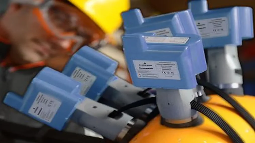
- Continuous monitoring: Involves the use of sensors and automated systems to provide real-time data on the condition of the pipeline system. Continuous monitoring is beneficial in detecting sudden changes or aggressive corrosion developments in high-risk areas, allowing immediate action to be taken in terms of understanding the causes and normalizing conditions. This type of monitoring relies on permanently installed monitoring systems, such as ultrasonic transducers, guided wave transducer rings, thermographic cameras, among others, which transmit information about the condition of the pipeline on a continuous basis. Figure 1 shows an example of ultrasonic sensors that continuously measure pipe thickness and remotely receive thickness data via wireless transmission.
- Periodic monitoring: Consists of scheduled inspections and evaluations using techniques such as ultrasonic testing or radiography. It is less expensive, but may not detect rapid changes in corrosion rates between inspections.
Benefits of condition monitoring to prevent failures
The main benefit of condition monitoring is the ability to predict failures before they occur, through a proactive approach that enables accurate planning for timely maintenance and repairs, reducing the likelihood of catastrophic events. In addition, condition monitoring helps extend the life of pipeline systems and improves overall operational efficiency.
How to select points for process piping condition monitoring?
The assignment of the CML should be based on the specific damage mechanism that can potentially develop in the pipeline. Documents such as API 574 and API 571 serve as a guide to predict the damage mechanism. A CML corresponds to a “condition monitoring location” which is an area of the pipeline, such as a pipe section, bend, or other fitting, where multiple measurements can be made. Welds may also be designated as CMLs if the potential damage mechanism to develop is, for example, stress cracking.
The CML should not be confused with “test points”, which are specific locations where individual readings are taken corresponding to small points to perform, for example, ultrasonic thickness measurements, which should be well identified in order to always perform these measurements at the same locations, in order to reliably measure the rates of change of condition (pipe thickness).
Pipeline service classes
Prior to defining the locations for condition monitoring, process pipelines must be classified according to the degree of potential consequences in case of failure, except for pipelines that have been planned based on the RBI methodology. Based on the potential consequences and as established in API 570, the service classes of pipelines are:
- Class 1: Represents the services with the greatest potential to result in an immediate emergency should a pipeline leak occur. Examples of pipeline services within this class are:
- Flammable services that can self-cool and cause brittle fractures.
- Pressurized services that can vaporize rapidly during release, creating vapors that can accumulate and form an explosive mixture, such as C2, C3, and C4 streams.
- Hydrogen sulfide (more than 3 % by weight) in gaseous stream.
- Anhydrous hydrogen chloride.v
- HF acid (e.g. in HF alkylation units, as discussed in API 751, etc.).
- Pipelines over or adjacent to water and pipelines over public roads.
- Class 2: Services not included in other classes are in Class 2. This classification includes most unit process piping and selected external piping2.
- Class 3: These are services that are flammable but do not vaporize significantly when leaking, i.e. below the flash point, or flammable, but are located in remote areas and operate below the boiling point.
- Class 4: These are essentially non-flammable and non-toxic services, as are most utility services with no environmental or safety impact.
Adding more CMLs in appropriate locations to higher consequence pipelines subject to higher corrosion rates or localized corrosion and monitoring those CMLs more frequently can reduce the likelihood of high-consequence events3.
Criteria for CML assignment
To decide on the location, as well as the type and number of CMLs, the historical results of previous inspections, the typical corrosion and damage patterns expected in the pipeline, and the possible consequences in the event of a loss of containment should be taken into account.
In situations where the service produces a uniform type of corrosion, such as sulfide corrosion, the number of CMLs required to monitor a circuit will be less than those required to monitor circuits subject to more localized metal loss. This scenario requires greater attention due to the acceleration of damage, for which appropriate non-destructive testing (NDT) techniques are needed to generate corrosion mapping to ensure pitting identification and sizing.
In pipelines where water stagnation may occur, an inspection program might emphasize low points to monitor for carbon dioxide corrosion (CO₂), corrosion below the reservoir, or microbiologically influenced corrosion (MIC)1. Where fluid velocities and/or solids content make erosion the most likely threat to integrity, locations of velocity change, such as bends, would provide the most useful inspection data.
CMLs should be distributed throughout the piping system to provide adequate monitoring coverage of all types of components and fittings. CML thickness measurements are intended to establish general and localized corrosion rates in different sections of piping circuits2.
In any case, all such decisions should be consulted with the corrosion specialist.
Corrosion Under Thermal Insulation (CUI)
In the selection of the CMLs for detection and evaluation of CUI, certain aspects that could indicate the development of this damage mechanism should be considered, among which are the following.
- Visual condition of exterior sheathing and insulation, rust stains, biological growth, waterproof coating, bulging, dented or punctured.
- Evidence of fluid leakage (e.g., drips or vapors).
- Evidence of wet insulation areas.
- Low points of sagging lines.
- Bottom of vertical pipe.
- Proximity to equipment that could increase local humidity (e.g., cooling towers).
- Area where temperature regimes move in and out of the temperature range susceptible to CUI.
- Piping components (e.g., nipples, nipples, nozzles, supports, and dead legs) that are part of the piping system but penetrate the insulation or may pass into the CUI range.
Mixing points: Areas of special interest are mixing points, which are locations in piping systems where two or more different streams meet. The difference in composition, temperature, or any other parameter in the streams encountered can contribute to deterioration, accelerated or localized corrosion, and/or thermal fatigue during normal or abnormal operating conditions.
Injection points: Injection points are designated locations where operators can inject chemicals into a process stream to prevent or mitigate corrosion or cracking. Injection points may be subject to accelerated and/or localized damage due to normal and abnormal operating conditions.
Methods applied for condition monitoring
Non-Destructive Testing (NDT) methods are commonly used to evaluate the condition of piping systems without causing damage, the choice of method depends mainly on the type of corrosion. The following are some of the most important ones to consider:
Ultrasonic (UT): This method is effective for detecting thinning caused by uniform corrosion. These measurements are made at the “examination points” already defined in the pipe section or fittings to monitor the loss of thickness.
UT is also suitable for weld crack detection. Pulse echo techniques, or more advanced techniques such as Phase Array Ultrasonic Testing (PAUT) or Time of Flight of Diffracted Wave (TOFD), are appropriate for this purpose. TOFD is more appropriate for tracking crack evolution when applying methodologies such as Fitness For Service (FFS).
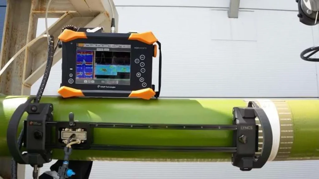
Corrosion mapping with PAUT: It is suitable for the detection and evaluation of localized corrosion zones by providing quantifiable images of both the cross-section of the pipe (B-Scan) and a plan view of the pipe (C-Scan). An example of corrosion mapping by PAUT is shown in figure 2.
Industrial Radiography (RT): It can be used to identify pitting and localized corrosion, it is ideal in insulated pipelines for CUI inspections (Tangential Radiography for the evaluation of insulated outer wall pitting), being the Digital Radiography (DR) technique special for the latter condition. RT can also be used for weld crack detection.
Eddy currents (ECT): This technique within the electromagnetic test method applied to non-ferromagnetic materials is effective for detection and evaluation of surface or near-surface defects and weld cracking. In relatively low thicknesses, the detection includes those discontinuities within the volume and close to the internal surface of the test piece.
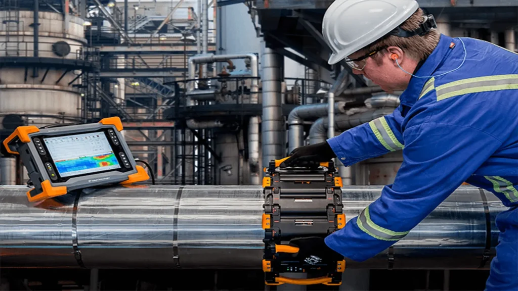
Pulsed Eddy Current Array (PECA): This advanced variant of the Eddy Current Technique (ECT), and evolution of Pulsed Eddy Current (PEC), is suitable for identifying areas of corrosion under thermal insulation (CUI), with a color scale visualization of the surface below it (C-Scan), giving a close estimation of the remaining thickness. Once the corroded zone is detected, removal of the insulation may be required for a more detailed evaluation of the external corrosion of the pipe with pit-gage, 3D laser method, or UT thickness measurement. An example of PECA application is shown in figure 3.
Guided Wave Testing (GWT): Guided wave testing is used for the detection of changes in cross-sectional area indicative of metal loss and is ideal for CUI and difficult-to-access pipe sections such as sections under bridges or overhead pipelines such as header lines at distillation tops. Through more advanced techniques such as Short Range Guided Waves (SRGWT) and the use of Electromagnetic Acoustic Transducers (EMAT), the degree of corrosion (thickness loss) can be quantified, making it ideal for applications such as Corrosion Under Pipe Support (CUPS) assessment.
Infrared Thermography (IRT): Ideal for temperature monitoring in certain piping systems where an increase in the operating temperature value may promote a corrosion mechanism. Infrared thermography also allows locating areas with possible moisture accumulation in the external thermal insulation of the pipeline by detecting lower temperatures, which helps to define CMLs for CUI evaluations.
Direct and intrusive corrosion monitoring techniques
Direct and intrusive or fluid contact corrosion monitoring techniques, through physical means such as test coupons or mass loss and electrical resistance, or through electrochemical means (electrodes) such as linear polarization resistance (water and gas + water service) and electrochemical noise, are very useful for corrosion monitoring.
Through the use of test coupons it can be determined, apart from the corrosion rate, the damage mechanism that is affecting the pipeline. Techniques such as linear polarization resistance have the ability to measure the corrosion rate at the instant of corrosion.
Other tests such as Penetrant Testing (PT) and Magnetic Particles (MT) can also be used for condition monitoring, however, they are limited to the detection of in-service faults that have already advanced through the pipe material and are therefore not effective for early detection of these discontinuities.
Advanced strategies for corrosion monitoring
IoT (Internet of Things)-based monitoring technologies
The integration of this technology allows continuous data collection from permanent sensors located in the CMLs. These fixed sensors, such as ultrasonic transducers for UT thickness gauging and transducer rings for GWUT, transmit data wirelessly and continuously, enabling real-time analysis and remote corrosion monitoring. IoT-based systems can detect anomalies early, triggering alerts for maintenance teams to act before a failure occurs.
Use of Artificial Intelligence for predictive corrosion analysis
Artificial intelligence (AI) can process large amounts of data generated by IoT sensors to predict future corrosion trends. Machine learning algorithms analyze historical corrosion data, operating conditions, and environmental factors to identify patterns and make predictions about when and where corrosion is likely to occur. This predictive capability allows operators to schedule maintenance more effectively and reduce the risk of unexpected failures.
The following video shows the advantages of the gPIMS permanent installation monitoring system; which is a GWT sensor that is permanently installed in the pipeline. Courtesy of: GUL – Guided Ultrasonics Ltd.
Advanced sensors for corrosion detection
The development of advanced sensors, such as electrochemical and fiber optic sensors, has improved the accuracy and reliability of corrosion detection. These sensors can provide real-time data on factors such as pH, humidity, and temperature, which influence corrosion rates. Fiber optic sensors, in particular, are highly sensitive and can detect minute changes in the environment that can signal the onset of corrosion.
Conclusion
Effective corrosion monitoring in process piping systems requires a strategic approach to the selection of condition-monitoring locations. By focusing on high-risk areas, utilizing advanced monitoring technologies, and implementing best practices through corrosion training, organizations can significantly reduce the risk of corrosion-related failures. Although challenges exist, the long-term benefits of continuous monitoring far outweigh the costs, making it a critical component of modern asset management strategies.
References
- VIKING ENGINEERING. Choosing & Using Condition Monitoring Locations (CMLs); Accessed October 01, 2024. https://www.gate.energy/the-brainery/choosing-amp-using-condition-monitoring-locations-cmls
- AMERICAN PETROLEUM INSTITUTE. API 570, Piping Inspection Code: In-service Inspection, Rating, Repair, and Alteration of Piping Systems; Accessed October 02, 2024.
- AMERICAN PETROLEUM INSTITUTE. API 574, Inspection Practices for Piping System Components; Accessed October 03, 2024.