In the industrial sector, effective corrosion management is essential to preserve the integrity of assets. In this context, corrosion mapping is presented as a key tool, especially in assets prone to corrosion due to internal pits and cracks. This method allows you to accurately identify and evaluate vulnerable points, providing information to implement preventive and maintenance strategies.
Corrosion represents a significant threat to the integrity of industrial assets, causing structural deterioration, increased maintenance costs and potential safety risks. Among the different types of severity, corrosion due to internal pitting and cracks are located in specific areas that are difficult to predict, making it difficult to detect, especially if it develops under the coatings on the surface to be inspected.
This article addresses topics such as: the challenges posed by internal pitting and crevice corrosion, traditional detection methods, and advances in automated electromagnetic technologies integrated into corrosion mapping.
Corrosion mapping in metallic structures
Corrosion mapping consists of a two-dimensional representation through a C-Scan presentation, it is a method used to characterize areas affected by internal corrosion. It provides an easy-to-interpret image and quantitative results, in addition to allowing the detection and sizing of pits and cracks on metal surfaces using the techniques used.
In general terms, it is a tool applied in monitoring , identification and location of areas affected by corrosion in components, parts or metallic structures subject to inspection. This method is not only limited to indicating the presence of corrosion, but also covers important aspects, such as:
- Classification of corrosion according to its morphology or type.
- Evaluation of the degree of affectation of the area.
- Quantification of the level of corrosion based on the mechanical properties of the material.
- Estimation of the possibility of repairing the detected corrosion.
- Location of faults, defects or discontinuities that could become potential corrosion zones in the short term.
- Macroscopic evaluation of the condition of the component, part or structure.
- Assessment of the effectiveness of the applied products that have shown failures.
This comprehensive mapping process provides information on the presence of corrosion on metal components and also offers detailed analysis for informed decision-making regarding asset management and maintenance. Challenges against corrosion due to internal pitting and cracks.
Internal pitting corrosion occurs when localized areas on the internal surfaces of assets, such as pipes, storage tanks, and vessels, exhibit confined space corrosion. Unlike general corrosion, which spreads uniformly over a surface, pitting and crevice corrosion can compromise the structural integrity of the material.
The challenge lies in detecting this type of corrosion before it leads to catastrophic failure. Pitting under coatings can be a challenge for Phased Array Ultrasound (PAUT) corrosion mapping, and the presence of cracks is impossible to show on a C-Scan presentation for this same technique.
Traditional detection methods
- Visual Inspection (IV): Visual inspection is a fundamental method for corrosion detection, but has limitations when it comes to internal pitting corrosion. Corrosion can be hidden under coatings or in hard-to-reach areas, making it difficult to identify with the naked eye.
- Ultrasonic Testing (UT): Ultrasonic testing involves sending high-frequency sound waves through a material to identify areas of corrosion. While effective in many scenarios through advanced techniques such as Phased Array Ultrasound (PAUT), in some cases ultrasonic testing may not offer sufficient performance or be sensitive enough to detect pits very small in diameter and impossible in the Capture of cracks in a C-Scan presentation.
- Radiographic tests: Radiographic tests use x-rays or gamma rays to capture images of internal structures. However, this method presents certain drawbacks for its application such as: safety, limited accessibility and limitations to detect pitting corrosion in early stages.
Advances in electromagnetic technology
In recent years, electromagnetic technology has emerged as a powerful tool for corrosion mapping in internal pit detection as well as crack pickup. These advances take advantage of the principles of electromagnetic induction to detect and quantify corrosion without the need for direct contact with the material.
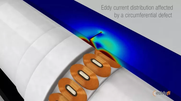
Eddy Current Test (ECA)
Eddy current testing involves inducing electrical currents in a conductive material and measuring the resulting magnetic fields. Changes in conductivity, such as those caused by pitting corrosion, are detected and analyzed. This non-destructive method can be applied to a variety of materials and in various shapes such as tubes and sheets.
Modern technologies such as Induced Currents by Sensor Arrays (ECA), allow mapping in components such as tubes, containers, storage tanks, turbine parts, among others, being very sensitive to the detection of pits and cracks. This technology generates more consistent results than manual raster scans, thus decreasing operator dependency.
Eddyfi Technologies ECA probes use multiplexing, which involves turning coils on and off in specific sequences to take advantage of the width of the probe. Multiplexing also minimizes interference between closely spaced coils (mutual inductance) and maximizes probe resolution.
The following video shows the application of Eddyfi Technologies ECA probes on pipes.
Magnetic Flux Leakage (MFL)
MFL is a rapid, reliable corrosion detection technique that detects the volume of missing magnetic material in a component under inspection. MFL involves magnetizing a ferromagnetic material and measuring flux leakage caused by defects such as corrosion and/or presence of cracks.
This method is particularly useful for exchanger and boiler tubes, as well as for the specific evaluation of storage tank floors, offering comprehensive corrosion mapping, it can also be applied to coatings.
Eddyfy technologies offers the new FloormapX with unique innovative features such as precision active steering for fast, high-quality curved scans in the critical zone, an interactive laser guide to easily correlate the physical locations of tank floor defects with C-scan images, powerful onboard lighting and SmartMAGNET™ for optimized inspection performance depending on plate thickness.
MFL inspections are a quick and cost-effective resource for tank floor evaluations. This method temporarily magnetizes the bottom of the tank, generating a magnetic field. Disturbances in the magnetic field indicate failures in the structure.
Alternating Current Field Measurement (ACFM)
It is a completely quantitative electromagnetic technique that allows detecting and characterizing surface (ferromagnetic metals) and subsurface (ferromagnetic and non-ferromagnetic metals) cracks under non-conductive coatings quickly and reliably.
The technique is aimed mainly at detecting cracks and with the use of probes with sensors arranged in an array, a larger area can be inspected and displayed in a C-Scan presentation, being advantageous in those cases where cracking is the main degradation mechanism. expected, such is the case of the detection of fatigue cracks in underwater structures that support marine platforms.
In inspections of storage tank floors, ACFM is used as a complement to the MFL in the evaluation of welded joint areas and with advantages over other traditional tests such as the vacuum box test, which is difficult to apply in overlapping welds. or near obstructions, and magnetic particles when it is required to remove the coating (epoxy) for the effective application of the test, since cleaning and re-application of the protective layer makes it much more expensive than doing the inspection with ACFM.
Benefits of electromagnetic corrosion mapping
- Non-destructive: Electromagnetic techniques are non-destructive, meaning they can assess the extent of corrosion without causing damage to the asset, which is critical to minimizing downtime and preserving the structural integrity of the material.
- High sensitivity: Electromagnetic methods show high sensitivity to small changes in material properties, being suitable for detecting pitting corrosion in early stages and crack development. This allows for proactive maintenance and avoids costly repairs.
- Versatility: Electromagnetic technology can be applied to a wide range of materials and asset types. Whether inspecting pipelines, storage tanks, pressure vessels, or critical infrastructure, these methods offer versatility in corrosion mapping.
Conclusions
Automated corrosion mapping has become an integral part of NDT inspection and has been widely adopted in corrosion management programs. The new technologies integrated into the tests of: Induced Currents with Sensor Array (ECA), Magnetic Flux Leakage (MFL) and Alternating Current Field Measurement (ACFM), offer detailed and timely mapping of corrosion. This precision facilitates a proactive approach to maintenance, ensuring the integrity and operational efficiency of industrial assets.
References
- JC DRURY I. Magnetic flux leakage technology; Consulted on January 23, 2024. https://www.eddyfi.com/doc/Downloadables/magnetic_flux_leakage_technology-01.pdf
- SHANNON P. FARRELL, MARTIN LUGG, AND KYLE AVERY. Application of Alternating Current Field Measurement for Determination of Surface Cracks and Welds in Steel Structures at Lift-of; Consulted on January 24, 2024. https://cradpdf.drdc-rddc.gc.ca/PDFS/unc199/p802467_A1b.pdf
- CHARLES TREMBLAY. Safeguarding Storage Tanks by Scanning Welds with ACFM; Consulted on January 24, 2024. https://blog.eddyfi.com/en/safeguarding-storage-tanks-by-scanning-welds-with-acfm
- MATHIEU BOUCHARD. Surface Eddy Current Array: The Unsung Hero of Corrosion Mapping; Consulted on January 25, 2024. https://blog.eddyfi.com/en/author/mathieu-bouchard
- JC DRURY I, A. MARINO. A Comparison of the Magnetic Flux Leakage and Ultrasonic Methods in the detection and measurement of corrosion pitting in ferrous plate and pipe; Consulted on January 25, 2024. https://www.ndt.net/article/wcndt00/papers/idn701/idn701.htm