
Table of Contents
- Cavitation and its mechanism
- Detection and diagnosis
- Types of cavitation in pumping systems
- Thermodynamic and fluid-dynamic fundamentals
- Equipment susceptible to cavitation
- Predictive strategies, design and operations
- Vapor formation dynamics and fluid behavior: keys to prevent cavitation
- Effective strategies to prevent cavitation and maximize pump life
- Conclusions
- References
Cavitation is a hydrodynamic phenomenon characterized by the formation, growth and implosive collapse of vapor bubbles in a fluid. In pumping systems, this phenomenon occurs when the local pressure of the fluid drops below its vapor pressure at the operating temperature, inducing a phase change from liquid to vapor, generating microcavities that, when transported to areas of higher pressure, suddenly collapse.
The collapse of these bubbles produces localized shock waves with extremely high transient pressures (up to 10,000 bar) and high-velocity microjets that impact metal surfaces, causing erosion, vibrations and characteristic noise. A thorough understanding of cavitation, its causes and effects, allows engineers to implement appropriate preventive measures, such as maintaining optimum inlet pressures and making modifications to pump designs.
NPSH control is key to avoiding cavitation and maximizing the life of a centrifugal pump. Proper pump selection and design, along with proper installation and maintenance, will allow the pump to operate within safe ranges, minimizing the risk of failure and improving the overall efficiency of the pumping system. This phenomenon represents one of the most destructive failure mechanisms in industrial pumping systems.
Cavitation and its mechanism
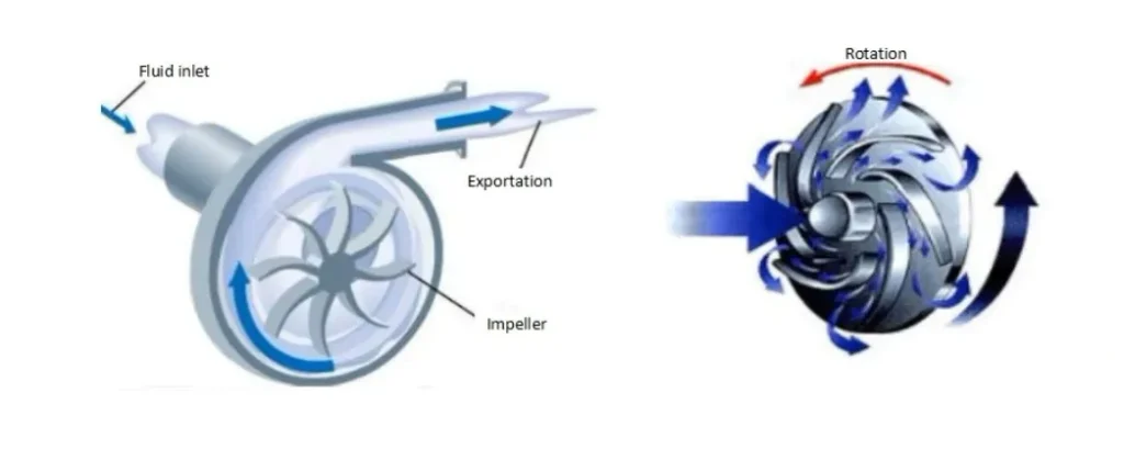
Cavitation is a complex and damaging phenomenon that affects the performance and mechanical integrity of centrifugal pumps. It is a two-phase process that occurs when there is a significant drop in liquid pressure in specific areas of the hydraulic system, especially when passing through the impeller.
The cavitation mechanism begins when the fluid pressure drops below its vapor pressure, causing vapor bubbles to form at the impeller inlet. This initial stage typically takes place at the impeller eye, where the fluid is subjected to a sudden acceleration and, as a consequence, a reduction in pressure.
As the impeller rotates, the bubbles move into regions of higher pressure along the blades. At that point, the bubbles collapse violently in a process known as implosion. These implosions generate high-energy shock waves capable of exceeding the elastic limit of the materials that make up the pump, particularly the impeller.
The result of this phenomenon is localized damage in the form of pitting or cavities in the metal surface, especially at the leading edges of the blades. Over time, this deterioration intensifies if cavitation is not controlled, affecting not only the impeller but also, in extreme cases, the pump casing.
In addition to physical damage, cavitation is accompanied by characteristic operating symptoms: gravel-punching noises, high levels of vibration and a noticeable decrease in the head generated by the pump. As the phenomenon worsens, these effects intensify, leading to loss of efficiency, increased maintenance costs and even catastrophic machinery failure.
Detection and diagnosis
The presence of cavitation can be identified by the following indicators:
- Acoustic indicators: Characteristic high-frequency noise (>1 kHz), similar to gravel flow (rocks).
- Mechanical indicators: Irregular high-frequency vibrations, measurable by spectral analysis.
- Hydraulic indicators: H-Q curve degradation with pronounced drop in performance, pressure and flow fluctuations.
- Thermal indicators: Localized temperature increase due to energy released during bubble collapse.
- Physical manifestations: Characteristic erosion in low pressure zones (typically blade suction face), with honeycomb or spongy surface pattern.
Types of cavitation in pumping systems
- Suction cavitation: Occurs at the impeller inlet due to insufficient NPSH.
- Discharge cavitation: Occurs on the back face of the blades, generally in operating conditions far away from the optimum point.
- Recirculation cavitation: Associated with secondary flows under partial load or overload conditions.
- Vortex cavitation: Generated by suction vortices that can entrain air.
- Flow separation cavitation: Occurs when the fluid cannot follow the contours of the impeller due to inadequate geometries or transient regimes.
Thermodynamic and fluid-dynamic fundamentals
Cavitation is governed by the relationship between two fundamental parameters:
1. Available NPSH (NPSHA): Represents the energy available in the system to prevent vaporization of the fluid, expressed as:
NPSHa = P₁/γ + v₁²/2g – Pᵥ/γ
Where:
P₁ = Absolute pressure at pump inlet. γ = Specific gravity of the fluid. v₁ = Fluid velocity at suction. g = Acceleration of gravity. Pᵥ = Fluid vapor pressure at operating temperature.
2. Required NPSH (NPSHr): Minimum NPSH value necessary to prevent cavitation, experimentally determined by the manufacturer as the condition where a 3% drop in head is observed.
The safe operating condition requires that: NPSHa > NPSHr + Safety margin (typically 0.5-1.0 m).
As a complement to this information, this video courtesy of “The Ingenieering Mindset”, addresses the fundamental principles of net positive suction pressure (NPSH) in pumps, to facilitate the understanding of the phenomenon.
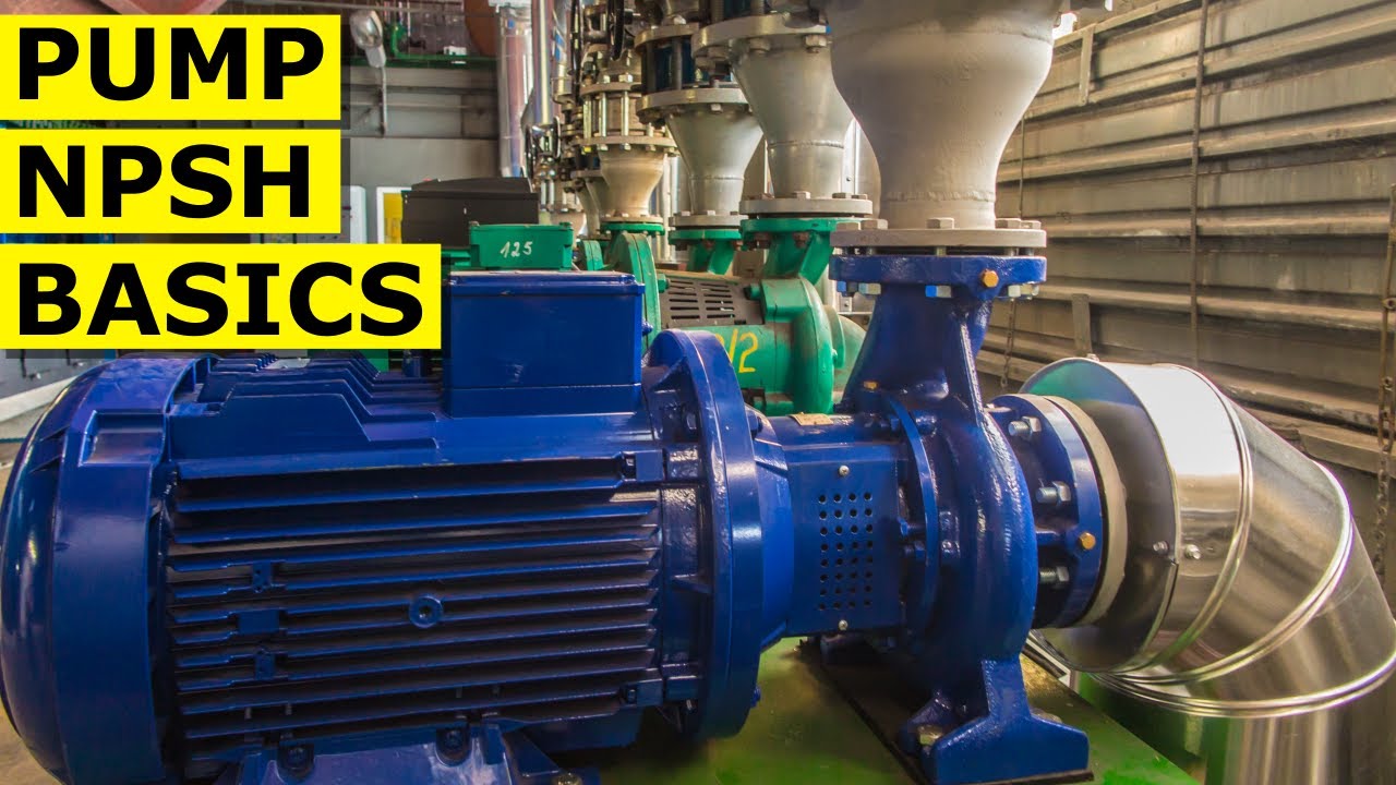
Net Positive Suction Pressure (NPSH) in pumps.
Equipment susceptible to cavitation
The susceptibility to cavitation varies according to the type of pump:
- Centrifugal pumps: Particularly vulnerable due to high peripheral speeds and steep pressure gradients. The incidence is higher in high specific speed designs (Ns>40) and when operating outside their BEP (Best Efficiency Point).
- Axial flow pumps: Extremely sensitive to marginal NPSH conditions due to their high specific speeds (Ns>80). Cavitation typically initiates at the blade tips where relative velocities are maximum.
- Positive displacement pumps:
- Gear pumps: Susceptible to cavitation at the gear points and at the transition between chambers.
- Screw pumps: Cavitation can occur in the spaces between the rotors and the casing.
- Piston/diaphragm pumps: Cavitation usually occurs during the suction phase, especially at high speeds.
Predictive strategies, design and operations
Analysis of pump characteristic curves
The analysis of the characteristic curves of a centrifugal pump is a fundamental tool to prevent phenomena such as cavitation and to optimize system operation. These curves -which relate the flow rate with the manometric head, the power absorbed and the efficiency- allow to evaluate the hydraulic behavior of the equipment under different operating conditions.
A correct interpretation of the H-Q curve (head vs. flow) allows identifying the Best Efficiency Point (BEP) and verifying if the system operates in conditions far from this point, which may induce hydraulic instabilities and facilitate the appearance of cavitation. Also, overlaying the Net Positive Suction Head Required (NPSH) curve with the available NPSH curve of the system is key to ensure that liquid vapor pressure is not reached.
Mitigation strategies include:
- Operating point adjustment: by redesigning the hydraulic system or changing the rotational speed.
- Proper pump selection: considering actual operating conditions and NPSH margins.
- Continuous monitoring of critical parameters: flow, suction pressure, vibration and noise.
- Use of variable frequency drives (VFD): to maintain operation within the stable zone and away from the cavitation regime.
The analysis of a pump’s characteristic curve allows to predict cavitation conditions, to make informed decisions in order to increase the reliability and efficiency of the industrial pumping system. For more information, please watch the following video courtesy of: Central States Industrial Equipment (CSI).
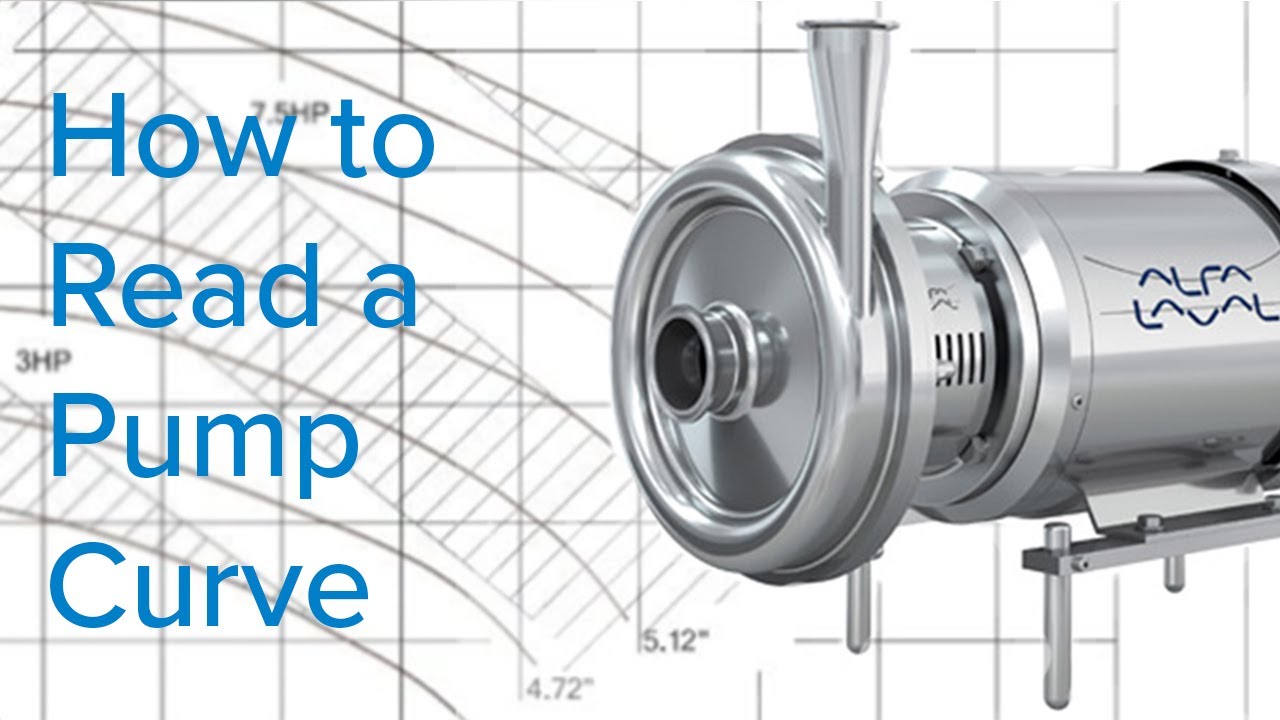
How to read the characteristic curve of a centrifugal pump?
Design and selection
- Selective oversizing:
- Calculate NPSHa considering critical conditions (maximum temperature, minimum level, maximum losses).
- Apply safety factor: NPSHa ≥ 1.3 × NPSHr for critical applications.
- Consider effects of viscosity and gas content in non-ideal fluids.
- Geometric modifications:
- Implementation of suction inductors (reduce NPSHr by up to 50%).
- Optimization of the inlet angle of the blades.
- Design of double suction impellers to balance axial loads.
- Erosion resistant surface treatments (stellite coatings, tungsten carbide).
- System configurations:
- Recommended minimum submergence in suction tanks: S ≥ 4D + 0.1v²/2g.
- Installation of vortex suppressors or baffle plates.
- Minimization of fittings in the suction line (elbows, valves, reducers).
- Oversized suction pipe (recommended velocity < 1.5 m/s).
Operating conditions
- Modification of operating parameters:
- Reducing the operating speed (NPSHr varies with the square of the speed).
- Increasing suction pressure by:
- Raising the suction tank level.
- Reduction of suction line losses.
- Installation of booster pumps.
- Fluid temperature control (every 10°C reduction significantly decreases Pv).
- Active control:
- Early detection systems through acoustic or vibrational monitoring.
- Control algorithms to avoid operation in critical areas.
- Flow regulation by means of frequency variators instead of throttling.
Vapor formation dynamics and fluid behavior: keys to prevent cavitation
Cavitation prevention in centrifugal pumps starts from an essential principle: avoiding the formation of vapor inside the pump body. This phenomenon occurs when the local pressure of the fluid drops below its vapor pressure, which induces the formation of vapor-filled cavities that, when transported towards areas of higher pressure, collapse violently. The collapse of these bubbles generates localized shock waves that impact directly on metallic surfaces, causing erosion, vibrations and, in severe cases, structural failure.
Influence of affinity laws on cavitation risk
When operational modifications are made to a centrifugal pump, such as increasing the rotational speed or changing the impeller diameter, affinity laws are applied. These laws allow estimating how the flow rate, delivery head and power consumption vary. However, an increase in speed or diameter also increases the required NPSH, because the liquid accelerates faster and the pressure at the impeller inlet may drop below the cavitation threshold. If the system is not designed to provide sufficient available NPSH, these changes may induce cavitating conditions. Therefore, before applying adjustments using affinity laws, it is essential to carefully evaluate their impact on suction hydraulics.
The susceptibility of a system to develop cavitation depends on multiple factors. From the fluid point of view, those with low specific gravity or high vapor pressure have a greater tendency to vaporize under pressure drops. On the other hand, operating conditions also play a determining role: frequent operation at low flow rates moves the pump away from its point of greatest hydraulic efficiency, which increases head losses and reduces the pressure at the impeller inlet. In addition, in pumps with excessive wear ring clearances, internal recirculation of hot fluid into the suction area can occur, promoting an unfavorable thermal environment and facilitating phase change.
The type of fluid and its vaporization behavior also directly influence the severity of cavitation damage. Single-component fluids, such as pure water, tend to generate more stable and energy-charged bubbles. Upon collapse, these bubbles release high-intensity micro-impacts that erode impeller blades at an accelerated rate. In contrast, hydrocarbon mixtures exhibit less aggressive behavior: their higher viscosity and lower tendency to vaporize generate less energetic bubbles, which reduces the magnitude of mechanical damage.
Understanding the interaction between hydraulic conditions, fluid properties and system design is essential to establish effective mitigation measures. These include proper selection of materials, rigorous control of available NPSH, correct sizing of components, and operation within optimum flow and pressure ranges. Only through an integrated approach is it possible to minimize the risk of cavitation and extend the life of rotodynamic equipment.
Factors that promote cavitation
The pressure inside a pump decreases from the suction flange to the leading edge of the impeller blades, and then increases rapidly once the liquid is inside the blades. This pressure reduction is due to:
- Friction losses in the flow path.
Acceleration of the liquid.
Inlet impact losses at the blade tips.
Additionally, operation at low flow rates significantly reduces impeller efficiency, which increases the liquid temperature and, consequently, its vapor pressure.
Cavitation prevention in centrifugal pumps starts from an essential principle: to avoid, at all times, the formation of vapor inside the pump body. This phenomenon occurs when the local pressure of the fluid drops below its vapor pressure, generating bubbles that collapse violently and damage internal components.
There are certain factors that increase the risk of cavitation. Liquids with low specific gravity or high vapor pressure are especially prone to cavitation, as are systems that frequently operate at low flow rates, where the impeller is not working at its optimum efficiency. Also, excessive clearances in the wear rings may favor the recirculation of hot fluid into the suction zone, mixing with cooler liquid and intensifying the formation of vapor inside.
The destructive impact of cavitation also depends on the type of fluid and the amount of vaporization that occurs. In general, single-component liquids, such as pure water, release more energy during bubble collapse, causing intense micro-impacts that accelerate the erosion of metal surfaces.
On the other hand, hydrocarbon mixtures, due to their higher viscosity and thermodynamic behavior, tend to vaporize less and generate less energetic collapses, so mechanical damage is generally less severe. Understanding these factors is essential to implement effective design, material selection and operational strategies to minimize the risk of cavitation and extend the life of the pumping system.
Effective strategies to prevent cavitation and maximize pump life
Cavitation remains one of the main operational challenges in pumping systems, as it can cause irreversible damage to centrifugal pumps, reducing their efficiency and service life. To prevent this phenomenon, it is crucial to understand the fundamental principles that cause it, such as pressure conditions, the nature of the fluid and the operating parameters.
Proper control of factors such as suction pressure, correct selection of available and required NPSH, and detailed evaluation of fluid properties are essential to avoid vapor formation inside the pump. Careful application of affinity laws when making operational adjustments, such as changes in rotational speed or impeller diameter, must be accompanied by a thorough analysis of their effects on hydraulic performance. In addition, preventive maintenance, including checking wear ring clearances and overhauling key components, plays a crucial role in extending system life.
Through proper operational planning, proper pump design and rigorous maintenance, the efficiency of centrifugal pumps can be maximized, minimizing the risk of cavitation and ensuring long-term reliable and cost-effective operation. Implementing these strategies not only reduces the risk of catastrophic failure, but also optimizes the overall performance of industrial pumping systems.
Conclusions
Cavitation in pumps is a phenomenon of concern in fluid engineering, with direct implications in the design, operation and maintenance of rotodynamic equipment. Its manifestation in centrifugal pumps and turbomachines can generate localized damage by bubble implosion, affecting the integrity of components such as impellers and casing, besides reducing the hydraulic efficiency of the system. However, under controlled conditions, cavitation can also be used functionally, as occurs in certain ultrasonic cleaning processes, where the action of microbubbles facilitates the removal of contaminants without the need for abrasives.
From an operational approach, the detection of this problem through vibration monitoring, acoustic analysis and control of hydraulic parameters is key to mitigate its effects and avoid premature failures. The implementation of design strategies that raise the available NPSH and optimize the suction geometry are also fundamental to prevent its occurrence. Understanding the mechanisms that cause cavitation allows protecting industrial assets and exploring its exploitation in specific applications. Its study remains a critical area within applied hydraulics and predictive maintenance in demanding industrial environments.
References
- Forsthoffer, W. E. (2005). Forsthoffer’s rotating equipment handbooks, Vol. 1: Fundamentals of rotating equipment. Elsevier.
- www.lawrencepumps.com/documents/news_vol1_i5_oct.pdf
- www.pumpfundamentals.com/pump_glossary.htm
- https://evodrop.com/
- Karassik, I. J. P., Messina, J. P., Cooper, P., & Heald, C. C. (2008). Pump handbook (4th ed.). McGraw-Hill.