Corrosion is one of the main factors in the deterioration of buried or submerged metallic infrastructures, representing significant economic losses in sectors such as oil and gas, chemical industry and water supply. To mitigate this problem, cathodic protection (CP) systems are implemented, which require continuous monitoring to ensure their effectiveness and prevent structural failures. In this context, test stations play an important role in the reliability of cathodic protection systems.
From an economic point of view, the implementation of efficient test stations minimizes expenses in unforeseen repairs and extends the useful life of critical assets, favoring long-term profitability. Additionally, in a context of strict industrial and environmental safety regulations, these stations allow compliance with international standards such as NACE SP0169 and ISO 15589-1, avoiding penalties and ensuring compliance with quality standards.
The purpose of this article is to analyze in depth the design, installation and maintenance of cathodic protection test stations, highlighting their role in the evaluation and control of CP systems. It will also address technological innovations that optimize their performance and contribute to a more efficient management of corrosion in critical infrastructures.
What is a test station and what is it used for?
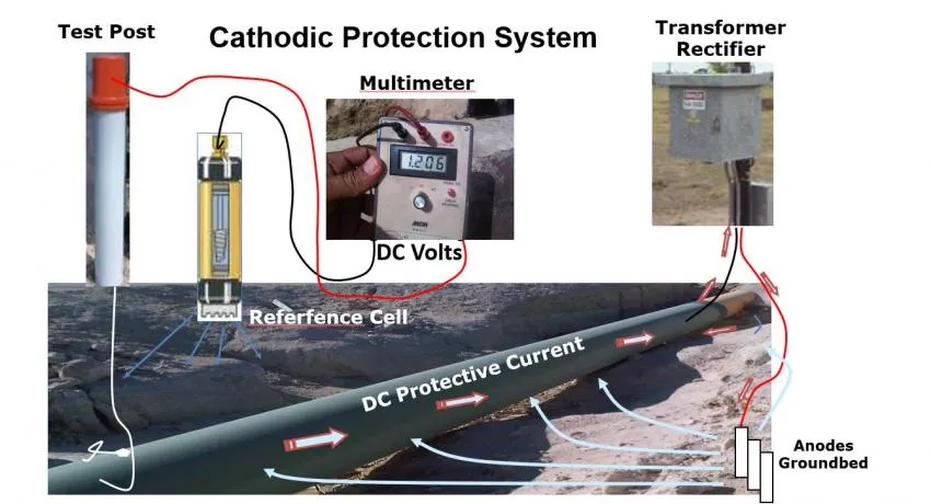
A cathodic protection (CP) test station is a strategic monitoring point designed for the measurement and evaluation of electrical parameters in cathodic protection systems. These stations are installed along the protected structure (oil pipelines, gas pipelines, tanks, marine structures, among others) and allow access to significant information for the validation and adjustment of the CP system. The following image shows the measuring pole integrated to the cathodic protection system of a pipeline, (figure 1).

These devices facilitate the verification of protection potential, current measurement, insulation assessment and detection of alternating current (AC) and direct current (DC) interference, play a key role in managing the integrity of structures, ensuring that the CP system operates within design parameters and complies with standards such as NACE SP0169 and ISO 15589-1.
Main functions
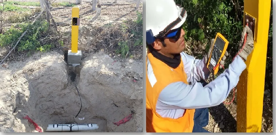
Cathodic protection test stations are fundamental devices in the management of the proper functioning of cathodic protection systems, allowing the measurement and evaluation of parameters such as protection potential, protection current and insulation integrity ( Figure 2). Their correct installation and maintenance ensure the useful life of the protected structures, and reduce operating costs by reducing corrective interventions and avoiding losses due to leaks, ruptures or failures in the infrastructure.

The test stations fulfill various specific functions for the control and maintenance of CP systems:
- Electrochemical potential measurement: These enable the level of protection achieved in the metallic structure to be evaluated in comparison with a reference electrode, ensuring that it is within the appropriate protection range according to standards such as NACE SP0169 and ISO 15589-1.
- Protection current monitoring: In impressed current systems, they facilitate the measurement of the current supplied by the rectifier and its distribution along the structure.
- Sacrificial anodes performance verification: They allow to evaluate the state and efficiency of galvanic anodes, measuring the potential difference between them and the protected structure.
- Electrical continuity assessment: They help to check the metallic continuity between different sections of the structure, avoiding losses of protection due to unintentional disconnections.
- Electrical interference detection: These allow identification and quantification of alternating current (AC) and direct current (DC) interference induced by power lines, electrified railroads or adjacent CP systems.
- Coating inspection: Through leakage detection testing (DCVG) or alternating current voltage gradient (ACVG), the integrity of the structure’s coating can be evaluated and flaws that may expose the metal to corrosion can be located.
Test station components
A typical test station consists of the following elements:
- Junction box (terminal): Made of weather-resistant materials (phenolic, reinforced polymers or treated metals), it protects the electrical connections and allows the installation of different test circuits.
- Reference electrodes: Used to measure the protective potential of the structure in relation to a stable reference (e.g. copper electrode/copper sulfate in soils or silver/silver chloride in marine environments).
- Connecting cables: Generally made of copper conductors with high resistance insulation, they connect the protected structure to the test station.
- Measuring connectors and resistors: They allow setting up specific test circuits, such as measuring the voltage drop across known resistors to determine the protection current.
- Polarization probes (in smart stations): Devices that allow to evaluate the real effectiveness of cathodic protection by minimizing errors due to current interference.
Classification of test stations
Test stations can be classified according to different criteria:
The construction material
- Steel test piles: Made of carbon steel or stainless steel, they offer high mechanical strength and durability.
- Cement test piles: Provide structural stability in soils of high chemical aggressiveness.
- Plastic test cells: Generally made of high-strength polymers, they provide a lightweight and corrosion-resistant option.
According to function
- Potential test station: Designed for the measurement of the electrochemical potential of the protected structure.
- Sacrificial anode test station: Allows the connection and performance monitoring of galvanic anodes.
- Current test station: Employed for current measurement in the CP system.
- Protection effect test station: Evaluates the continuity of protection along the structure.
- Intelligent test station: Integrated with sensors and data acquisition devices for remote monitoring and real-time analysis.
Design and installation of test stations
The process of designing and installing test stations begins with a detailed analysis of the technical and operational requirements of the system to be evaluated. For this purpose, the load capacity of the stations, the required measurement accuracy and the specific conditions of the test environments are considered. This is followed by the selection and procurement of the appropriate equipment, such as measuring devices, control systems and specialized software, in order to ensure the effectiveness and reliability of the tests.
The installation of the test stations is carried out under strict quality standards, ensuring that all components are correctly integrated and that the systems function optimally. Preliminary tests are also included to verify that the installed equipment and infrastructure comply with the parameters established in the design. Finally, a training process is conducted for the personnel in charge of operating the stations, ensuring that they can perform the tests efficiently and with the necessary knowledge to solve any eventuality.
Installation procedure
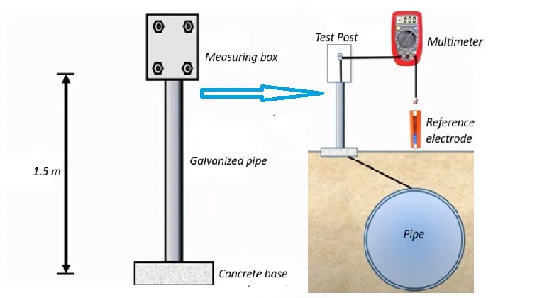
The installation must guarantee a firm and stable base to avoid inclinations or displacements. The use of protection posts or boxes is recommended in exposed areas; in general, the following elements are used in the field a concrete or concrete base in which a 1.5 m galvanized or galvanized pipe is inserted; a small box of different models is placed on top of the pipe where the cables of the buried structures are connected. A schematic representation of the installation process is shown in the figure 3.

The installation must ensure a firm and stable base to avoid tilting or shifting. The use of protective posts or boxes in exposed areas is recommended. The general procedure includes:
- Site selection: A representative point is chosen where the measurement accurately reflects the behavior of the CP system.
- Land preparation: The area is conditioned to ensure a stable base, avoiding areas prone to landslides or water accumulation.
- Test pile installation: Depending on the material selected, it is either buried or fixed on a concrete base to ensure stability.
- Cable connection: The measurement conductors are connected to the protected structure, ensuring continuity and avoiding false contacts.
- Terminal box assembly: A weatherproof box with accessible terminals is installed to facilitate taking measurements.
- Initial tests: Reference measurements are performed to verify the correct functioning of the test station before it is put into operation.
Maintenance and verification of test stations
Proper maintenance of test stations is essential to ensure continuous and effective operation of the cathodic protection system. Preventive maintenance and periodic checks ensure that the test stations continue to provide accurate and reliable data, which is key to the protection of metal infrastructures exposed to corrosion. This process includes a series of both inspection and measurement activities, which must be performed in accordance with established standards.
First, it is essential to perform periodic visual inspections of the test station to check the integrity of its components. This includes checking for structural damage to the terminal box, connecting cables and test stack. Environmental conditions, such as moisture, corrosion, or wear from exposure to weather, can affect the physical condition of the station, so any anomalies detected should be corrected immediately.
A crucial aspect of maintenance is the verification of electrical connections. Terminals and measurement leads should be cleaned regularly to avoid build-up of dirt or corrosion that could interfere with measurements. It is important to ensure that all connections are tight and free of corrosion, as any loss of contact or additional resistance can alter the accuracy of the data obtained.
Regarding measurements, it is essential to perform protection potential measurements at specific points of the structure to check that it remains within the expected values. These measurements should be compared with previous records to detect possible deviations, which may be indicative of a malfunction of the protection system. In addition, it is necessary to verify the resistance of the contacts and the continuity of the measuring circuits, which ensures that the readings are representative of the actual state of the protected structure.
Finally, maintenance of test stations should also include periodic recalibration of measurement equipment, as well as upgrading of monitoring systems if smart stations are used. These types of stations, which incorporate advanced devices such as polarization sensors, data acquisition modules and remote connectivity, require more detailed maintenance to ensure that data is transmitted correctly and in a timely manner.
Technological innovations in test stations
In recent years, due to major technological advances, cathodic protection test stations have undergone significant design changes. Recent innovations have improved measurement efficiency and data accuracy, facilitated remote monitoring and the integration of real-time analysis systems, optimized corrosion management and ensured proactive maintenance of critical infrastructure, reducing costs and improving operational safety.
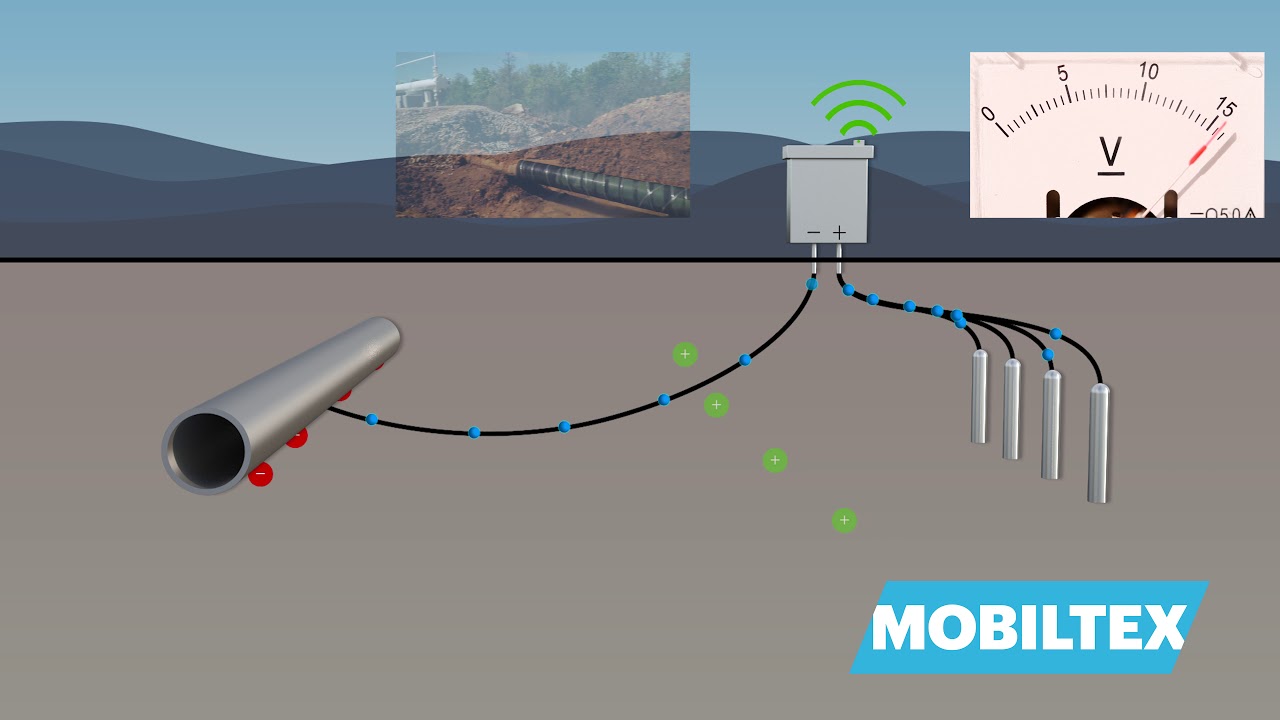
One of the most outstanding innovations is the incorporation of smart test stations, which are characterized by their ability to collect, process and transmit data automatically and remotely. Unlike traditional devices, which require frequent manual interventions for the measurement and analysis of cathodic protection parameters, smart stations allow continuous monitoring without the need for on-site personnel. This technology uses advanced sensors, such as polarization probes and reference electrodes, to measure the protection potential, protection current and other parameters in real time.

The main advantage of these smart stations is connectivity, which is achieved through the use of technologies such as GPRS, IoT and cellular networks. This allows data from the test stations to be accessible from any location, facilitating remote monitoring and informed decision-making in real time. This ability to transmit information in real time not only improves operational efficiency, but also enables early detection of potential failures or anomalies, reducing the need for corrective interventions and allowing preventive maintenance to be scheduled.
In addition, these smart stations often integrate data acquisition modules and storage systems that process and store the information collected during monitoring. This facilitates data traceability over time and the generation of detailed reports, which optimizes the management and performance analysis of cathodic protection systems. With GPS synchronization systems, the location of each station can be precisely tracked, which is especially useful in long pipelines and in areas that are difficult to access.
Another important innovation is the integration of advanced algorithms for predictive analysis. These algorithms can evaluate historical data from test stations and foresee possible failures or degradations in the cathodic protection system, allowing corrective actions to be implemented before significant damage occurs. This predictive capability represents an advance over traditional monitoring methods, which rely primarily on point measurements and lack the ability to anticipate problems before they occur.
Traditional test stations, although effective in their basic measurement function, require regular manual intervention to take readings and make the necessary corrections. In addition, their diagnostic capability is limited, as they rely primarily on potential and current measurements that must be interpreted by specialized personnel. Despite their reliability, these stations are more prone to human error, require more maintenance time and are less efficient in terms of long-term data collection.
Smart test stations, on the other hand, not only improve measurement accuracy, but also increase operational efficiency by enabling automation of the monitoring process. Thanks to their ability to perform continuous measurements, transmit data in real time and analyze system performance, these stations contribute to a significant reduction in operational and maintenance costs, as well as minimizing downtime of protected infrastructures.
Conclusions
The implementation of test stations in a CP system is essential to ensure continuous monitoring of the system and the integrity of the protected structure. Proper design and periodic maintenance optimize their performance, ensuring compliance with protection criteria and prolonging the useful life of industrial assets.
Continuous maintenance and verification are vital for the effective operation of cathodic protection test stations. These actions not only prevent operational failures, but also optimize the longevity of protected infrastructures and ensure compliance with safety and environmental regulations.
Technological innovations in cathodic protection test stations have marked a turning point in the way corrosion protection systems are managed and maintained. Smart stations, with their remote monitoring capabilities, predictive analytics and real-time data collection, offer key advantages over traditional devices, optimizing efficiency, reducing costs and improving the safety and reliability of critical infrastructure.
References
- Barton, M. (2015). Cathodic Protection: Theory and Practice. CRC Press.
- Payer, J. H. (2015). Handbook of Cathodic Corrosion Protection (4th ed.). NACE International.
- NACE International (2018). SP0169-2018: Control of External Corrosion on Underground or Submerged Metallic Piping Systems. NACE International.

