Table of Contents
- Pressure relief valve design requirements
- How to select relief valves in process plants?
- Pressure relief valves (PRV / PSV)
- When to apply API 520 or API 521?
- Technical comparison between API 520 and API 521
- Influence of backpressure on valve size
- Use of balanced valves according to API 520
- Application of API 520 to liquids, gases, and steam
- Real field errors in the application of API 520
- Case study: successful redesign of a relief system
- Conclusions
- References
The API 520 standard constitutes the fundamental technical reference for sizing pressure relief valves (PRV/PSV) in industrial facilities. Its correct application is critical to ensure the protection of pressurized equipment against overpressure scenarios, avoiding both catastrophic failures and unnecessarily conservative designs.
This standard covers the installation methods of pressure relief devices (PRD) for equipment that has a maximum allowable working pressure (MAWP) of 15 psig (1.03 barg or 103 kPAg) or higher.
Pressure relief valves (PRV) or rupture disks (RD) may be used independently or in combination to provide adequate protection against excessive pressure accumulation. As used in this standard, the term “pressure relief valve” includes safety valves used in services with compressible or incompressible fluids, and relief valves used in services with incompressible fluids.
The standard covers gas, vapor, steam, two-phase, and incompressible fluid services; it does not cover special applications that require unusual installation considerations.
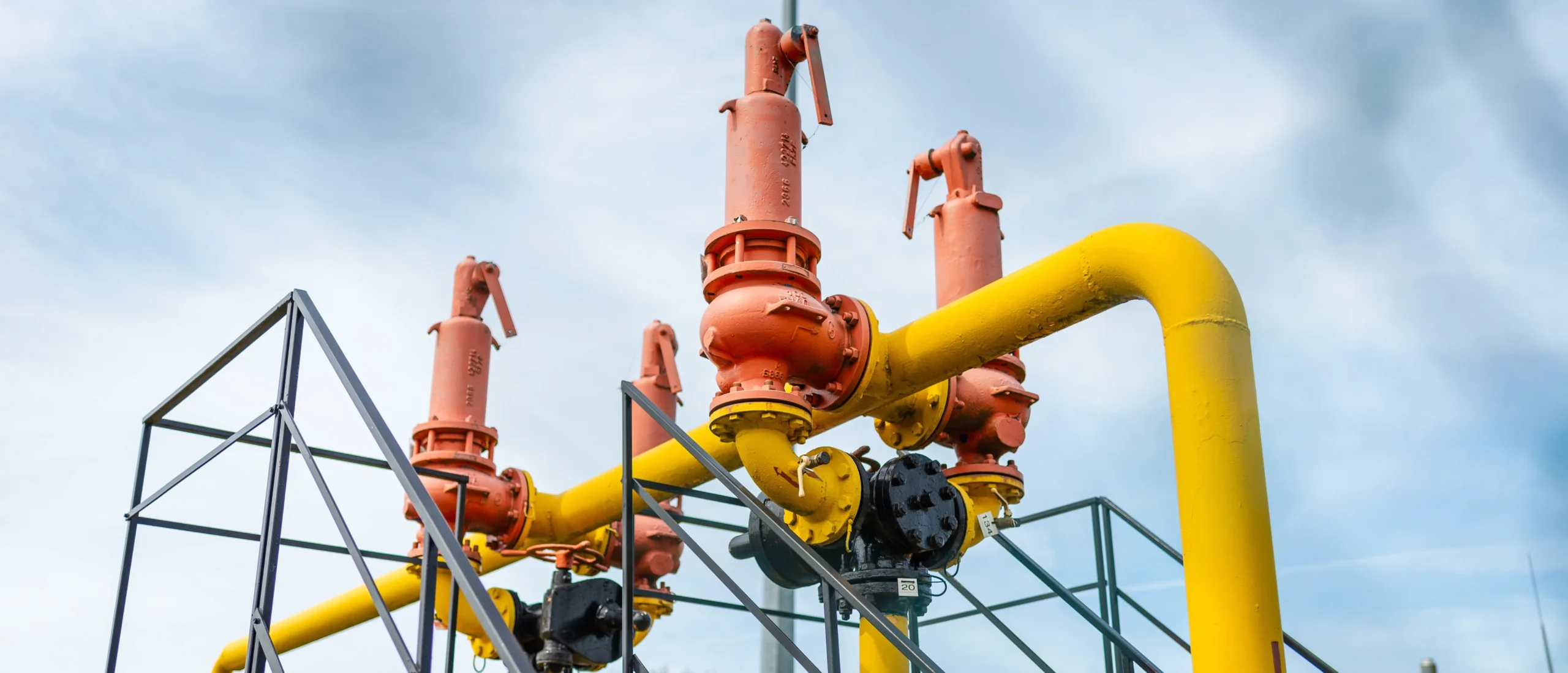
Image 1: stock-photo-a-pressure-safety-valve-psv-is-a-type-of-valve-used-to-quickly-release-gasses-from-equipment-in-2434053853
Pressure relief valve design requirements
From the API 520 perspective, the design of a relief valve must ensure that the pressure of the protected equipment does not exceed the permissible limits defined by the MAWP, even under the most severe and credible overpressure scenario. To achieve this, the valve must relieve the required flow rate while maintaining stable behavior during opening, relieving, and closing.
API 520 states that the relief scenario has already been correctly defined and validated. Therefore, its scope focuses exclusively on the hydraulic and thermodynamic sizing of the valve, including the selection of the orifice area, discharge coefficients, and applicable correction factors according to the type of fluid.
How to select relief valves in process plants?
In process plants such as refineries, petrochemical complexes, gas facilities, and midstream systems, relief valves must meet requirements that go beyond simple regulatory compliance. Selection must consider material compatibility with the fluid, extreme operating conditions, interaction with common discharge systems, and ease of maintenance throughout the asset life cycle.
A frequent engineering mistake is to assume that correct sizing guarantees adequate performance. In reality, incorrect selection of the valve type under real backpressure and operating conditions can seriously compromise the stability and reliability of the relief system.
Pressure relief valves (PRV / PSV)
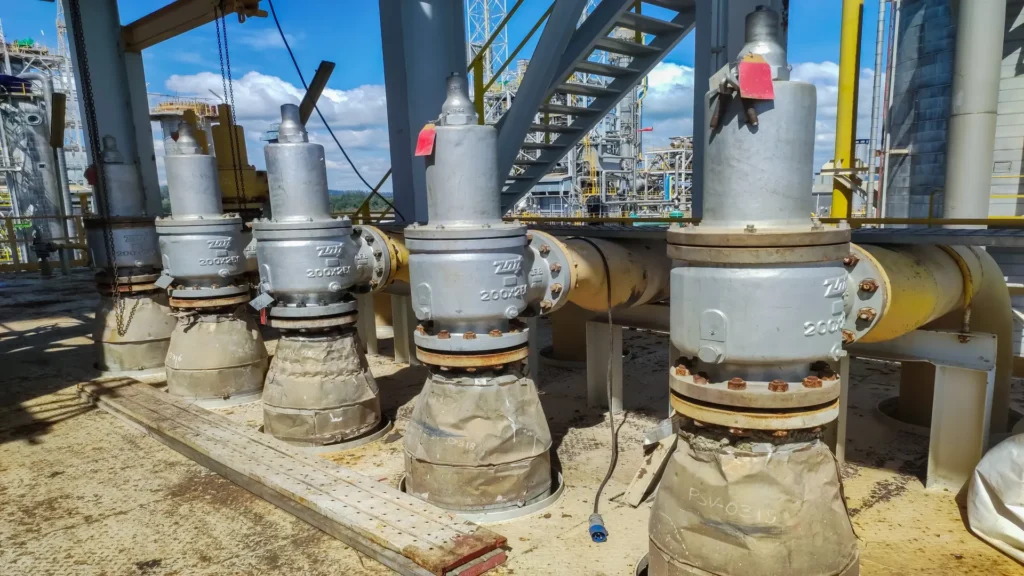
Although in industrial practice the terms PRV and PSV are often used interchangeably, both refer to automatic valves designed to safely relieve pressure when a predetermined value is exceeded. API 520 applies primarily to direct spring-operated valves, regardless of their commercial designation. The following image shows this type of valve.
What matters from an engineering standpoint is not the name, but the operating principle, the behavior under backpressure, and the certified capacity under real relief conditions.
When to apply API 520 or API 521?
A proper relief system design strategy requires a clear understanding of the difference between API 520 and API 521. API 521 focuses on identifying and evaluating credible overpressure scenarios, such as external fire, thermal blocking, control failures, thermal expansion, or runaway reactions. In contrast, API 520 is limited to defining the valve size required to relieve the flow associated with those scenarios.
Applying API 520 without prior analysis according to API 521 constitutes one of the most serious and common errors in industrial projects. The result is usually a valve correctly calculated for an incorrect scenario.
Technical comparison between API 520 and API 521
Understanding the functional difference between API 520 and API 521 is essential to avoid conceptual errors in relief system design. Both standards are complementary, but their scope, objectives, and level of analysis are clearly different. While API 521 defines the process safety framework and credible overpressure scenarios, API 520 is limited to sizing the valve that must respond to those scenarios.
From an engineering perspective, applying API 520 without prior analysis in accordance with API 521 is equivalent to correctly solving a poorly defined problem. The correct sequence must always begin with identification of the governing scenario and end with proper valve sizing.
The following comparison summarizes the most relevant technical differences from an applied engineering perspective:
| Aspect | API 520 – PSV Sizing | API 521 – Relief System Analysis |
|---|---|---|
| Main objective | Size the valve orifice area and relieving capacity | Identify and evaluate credible overpressure scenarios |
| Question it answers | What valve size do I need? | Why does overpressure occur and what is the worst-case scenario? |
| Technical focus | Hydraulic and thermodynamic analysis | Process safety and risk analysis |
| Type of analysis | Deterministic, equation-based | Evaluation of credible scenarios |
| Flow considered | Gas, vapor, and single-phase liquids | Single-phase and two-phase flow |
| Backpressure | Capacity and stability correction factors | Definition of discharge system architecture |
| Discharge system | Not covered | Includes piping, headers, and final disposal |
| Typical application error | Applying it without a validated governing scenario | Assuming it can replace API 520 |
Influence of backpressure on valve size
Backpressure is one of the most critical factors in the actual performance of a relief valve. API 520 distinguishes between superimposed backpressure, present before opening, and built-up backpressure, generated during relief.
Both types of backpressure directly affect the effective capacity of the valve, the opening pressure, and disc stability. A conventional valve subjected to high or variable backpressure levels may experience chattering, capacity loss, or permanent leakage, even when the orifice area calculation is correct.
Use of balanced valves according to API 520
Balanced valves, whether bellows- or piston-type, are used to minimize the influence of backpressure on valve behavior. API 520 allows their application when backpressure exceeds acceptable limits for conventional valves or when the system discharges to common headers with significant operational variations.
It is important to note that mathematical backpressure corrections do not eliminate mechanical instability issues. Therefore, selection of the valve type is a design decision just as relevant as calculation of the orifice size.
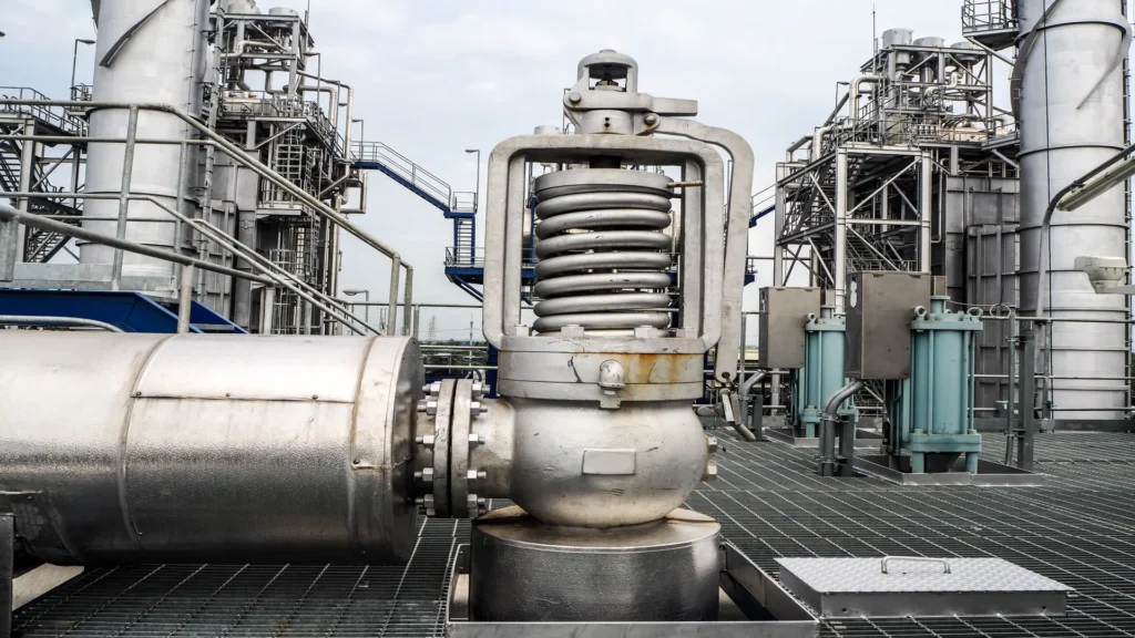
Image 2: stock-photo-safety-valve-in-power-plant-1260766246
Application of API 520 to liquids, gases, and steam
API 520 provides differentiated methodologies for sizing valves that relieve gases, steam, and liquids. In the case of gases and steam, the calculation is dominated by compressible flow, critical conditions, and pressure ratios. For liquids, incompressible flow requires a different treatment, where density, pressure drop, and hydraulic regime are the governing parameters.
One of the most frequent field errors is applying gas equations to liquid services under the argument of conservatism. This practice usually leads to oversized valves, excessive velocities, accelerated erosion, and long-term operational problems. API 520 explicitly differentiates between both approaches, and its correct application is essential for relief system reliability.
Real field errors in the application of API 520
Industrial experience shows that problems associated with relief valves rarely originate from a single cause. In most cases, they are the result of design decisions made in isolation, without a holistic view of the relief system. Some of the most recurrent errors observed in the field are discussed below.
A critical error is sizing a relief valve without adequate validation of the governing scenario. In multiple projects, thermal blocking has been selected as the sole design case because it is considered the most frequent, while external fire scenarios with significantly higher flow generation are ignored. The result is usually a valve correctly calculated for an incorrect scenario, incapable of protecting the equipment under extreme conditions.
Another recurring problem is underestimating the impact of variable backpressure in systems with common headers. In these cases, conventional valves correctly sized according to API 520 exhibit mechanical instability during relief, manifested as chattering, seat damage, and permanent leakage. This type of failure is not corrected by adjusting the orifice area, but by selecting a valve design suitable for the system architecture.
Finally, errors associated with incorrect application of flow models are common. The use of gas equations for liquid services, or failure to consider two-phase conditions, results in designs that comply on paper but fail in operation. These errors usually translate into excessive maintenance, loss of reliability, and repetitive operational events.
Case study: successful redesign of a relief system
A representative example of correct application of API 520 and API 521 corresponds to the redesign of the relief system of a hydrocarbon fractionation plant with a history of operational failures.
The facility had multiple relief valves discharging to a common header. Despite formally complying with the original calculations, frequent lift events, chattering, and high corrective maintenance costs were recorded. The initial analysis revealed that overpressure scenarios had not been revalidated since the original design phase.
The first step consisted of a comprehensive scenario review in accordance with API 521, identifying external fire as the true governing case. Subsequently, the valves were re-sized according to API 520, explicitly considering the built-up backpressure during simultaneous relief events.
As part of the solution, conventional valves were replaced with balanced valves, eliminating the critical influence of backpressure on mechanical performance. The result was stable operation, no chattering events, a significant reduction in corrective maintenance, and full compliance with allowable pressure limits under extreme scenario simulations.
This case confirms that correct application of API 520 depends not only on calculation, but on its coherent integration within a global process safety engineering strategy.
Conclusions
API 520 should be understood as a specialized tool within a broader discipline of relief system design. Its isolated application, without the support of a solid analysis in accordance with API 521 and proper selection of the valve type, inevitably leads to design errors.
When both standards are applied in a complementary manner, with sound engineering judgment and an understanding of real system behavior, it is possible to design robust, reliable relief systems aligned with best industrial practices.
API 520 represents a safety engineering discipline. Errors do not occur due to lack of calculation, but due to lack of technical judgment in interpreting the standard.
References
- https://www.api.org/~/media/files/publications/whats%20new/520_part2_e6