
Table of Contents
- What is Anodic Protection (AP)?
- Passivation Mechanism: Active-Passive Behavior
- Implementation of Anodic Protection
- Anodic protection system design arrangement
- Anodic protection system efficiency monitoring
- Anodic Protection (AP) vs. Cathodic Protection (CP)
- What are the most common applications of Anodic Protection?
- Conclusion
- References
Corrosion is a phenomenon that affects all metals, compromising their structural integrity and reducing them. However, science and technology have developed effective methods to combat it, among which anodic protection (AP), is presented as an effective method for corrosion control, however, it is a little-known technique with respect to cathodic protection (CP).
anodic protection (AP), which polarizes the metal towards a more positive potential, decreasing the corrosion rate to almost negligible levels in contrast to CP, which polarizes the metal towards a more negative potential. It has a much narrower field of application, specific for chemical environments. It is produced by keeping an active-passive metal in the passive zone by means of an externally applied anodic current, as explained graphically below.
The article highlights the importance of anodic protection (AP) in corrosion control, especially in chemical environments, as an effective but less known alternative to cathodic protection (CP). It explains how AP prolongs the life of metals by keeping them in a passive state and discusses technical concepts such as anodic passivity and active-passive behavior of materials. Finally, it seeks to inform professionals about the proper application of AP, despite its cost and maintenance challenges.
What is Anodic Protection (AP)?
Anodic protection (AP) is a method applied to control the corrosion of a metal surface by converting it into the anode of an electrochemical cell. This is done by polarizing the metal to a fixed potential more positive than the metal/dissolution equilibrium potential, controlling the potential over a range where the metal is passive. It is applied to protect metals that exhibit active-passive behavior in environments where the current density in the corrosion-free state is significantly higher than the current density in the passive state over a wide range of potentials1.
Concept of anodic passivity
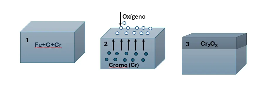
Anodic protection is a technique that involves the formation of a thin oxide layer on a metal to prevent corrosion, this process is known as anodic passivation and only occurs in materials with an active-passive behavior during polarization, such as: Titanium (Ti), Aluminum (Al), Chromium (cr), Hastelloy C, stainless steels with a high % of Cr, among others. These materials, when passivated, form an oxide layer spontaneously upon contact with air, thus acquiring a natural resistance to corrosion, as shown in figure 1. For anodic protection to be effective, the layer must be highly adherent and resistant.
This method is applicable only to passivable alloys having a wide range of passivation potentials. However, anodic protection requires expensive equipment and is difficult to maintain. Although its range of application is more limited compared to other methods, it may be the only viable technique in certain cases. If the protection fails, the alloy corrodes in the active region.
Passivation Mechanism: Active-Passive Behavior
Before going into the mechanism, it is important to understand the passivity phenomenon and where it occurs.
What is an active-passive metal?
Initially, at a current intensity io, it increases producing the dissolution of the material until reaching a value icr (critical current density); where the current density begins to decrease due to the formation of the passive layer until reaching a value ip (passivation current density).
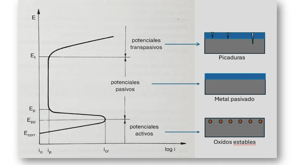
Figure 2, corresponding to the polarization curve of a passivating metallic material, is characterized by three clearly distinguishable domains: for the most negative potentials the current density increases with polarization: it corresponds to the anodic dissolution of the metal. For potentials above a well-defined value (Epp: primary passivation potential) the current density (ip) is reduced to a negligible value. Above this potential, the current density increases again with polarization due to the release of oxygen2.
For a metal to be protected, its potential must move to positive values up to the passivation zone. It is important not to exceed the transition potential between the passive and transpassive zones, beyond this zone pitting corrosion occurs. A typical feature of anodic protection is that the current source must provide high currents for the passivation process to occur, while only a small current is required to maintain protection.
Implementation of Anodic Protection
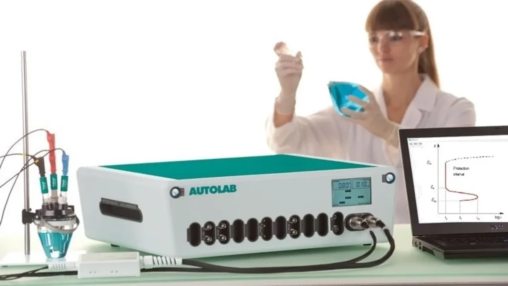
For the correct application of anodic protection, it is indispensable to know the design parameters and operating conditions, which are determined by means of experimental polarization measurements. For this purpose, specific equipment, known as potentiostatic (figure 3), and a detailed understanding of the passivation process are required. The protection potential is determined by means of the experimental potentiodynamic polarization curve.
The polarization curve of the material to be protected determines whether anodic or cathodic polarization is more suitable. If the system has a clearly distinguishable passive region, it can be protected anodically. The development of this curve is very important because it allows to know if the behavior of the material is passive-active and establishes the passivation potential range under which the structure should be maintained. Although initially high currents are needed to induce passivation, the maintenance of the protection consumes less energy, offering an efficient long-term solution.
In practice, specialized companies such as Corrpro Companies have developed anodic protection applications on passivable metal structures subjected to critical conditions, such as storage tanks, pipelines and stainless steel components. These systems are designed based on experimental data obtained from polarization curves and implemented with controlled current sources, ensuring that the metal potential is maintained within the passive region, thus reducing the likelihood of localized corrosion.
Anodic protection system design arrangement
According to the previous paragraph, the design parameters and operating conditions for the anodic protection are determined by experimental polarization measurements.
Figure 4, shows the typical arrangement of an impressed current anodic protection system for a steel storage vessel containing sulfuric acid. The power supply protects the storage tank by applying a constant potential between the tank and the Hg/HgSO4 (calomelane) reference electrode.
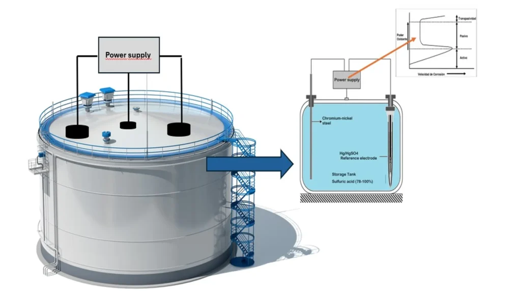
Anode protection systems are equipped with continuous proportional type controls3. The control measures the potential between the storage tank and the REF and compares the measured value to a preset optimum protection potential value. The system then sends a signal to the power supply to provide the required protective potential and current between the cathode and tank.
The REF potential is stable with respect to time and must not be polarized. Some standard REFs used for anodic protection are Hg/HgCl2, Hg/HgSO4 and Ag/Ag/Cl calomelane electrode. The potential in an anodic protection system is evenly distributed in the structure due to the low currents and high conductivity of the electrolyte. The current density flows between the storage tank and the chromium-nickel steel cathode.
The cathode must be inert in the corrosive solution and electrochemically stable. The resistance of the system is dominated by the cathode due to the large surface area of the anode and the high conductivity of the solution. To minimize hydrogen evolution and permeation in the bulk of the alloy, the cathode materials must have a low hydrogen surge. Examples of cathode materials that have been used in anode protection are chromium-nickel steel in 90-100% sulfuric acid.
Anodic protection system efficiency monitoring
Monitoring the effectiveness of anodic protection is carried out by regularly measuring the electrochemical potential of the metal, the resistance of the protective layer, and the current density. Specialized potentiostatic equipment and monitoring devices make it possible to verify whether the metal remains within the proper potential range for effective passivation.
Additionally, visual inspections and corrosion resistance tests are useful to assess the integrity and effectiveness of the protective oxide layer. Constant monitoring ensures that timely adjustments are made to the anodic protection system, ensuring its long-term performance.
Anodic Protection (AP) vs. Cathodic Protection (CP)
1.Principle of operation
- Cathodic Protection (CP): Works by polarizing the metal towards a more negative potential, which turns the structure into the cathode of an electrochemical cell. This prevents oxidation, protecting the metal from corrosion.
- Anodic Protection (AP): On the other hand, polarizes the metal towards a more positive potential, allowing the formation of a passive oxide layer that protects the metal. This process is effective on metals that exhibit active-passive behavior, such as titanium and certain stainless steels.
2. Ease of installation and initial costs
- Cathodic Protection: Generally easier to install; however, initial cost can be high, especially on large structures.
- Anodic Protection: In contrast, requires more complex installation, with specialized equipment that significantly increases initial costs. This is a limiting factor for its adoption in many applications.
3. Applications and environmental constraints
- Cathodic Protection: It is widely used in submerged and buried structures, such as pipelines and tanks, and is effective in a variety of environments. However, its effectiveness is reduced in environments with high resistivity, where the current supplied is insufficient.
- Anodic Protection: It has a more restricted field of application, being especially useful in chemical environments where the formation of a passive layer is paramount. It is not recommended in media with HCL or CL, where localized corrosion may occur.
4. Long-term maintenance and costs
- Cathodic Protection: One of the main advantages of CP is its low maintenance cost. However, in poorly coated structures or in seawater, high anode consumption can increase operating costs.
- Anodic Protection: Provides long-lasting protection, but requires rigorous maintenance to ensure its effectiveness. The system must be constantly monitored, as any uncontrolled activity could accelerate corrosion.
5. Protection efficiency
- Cathodic Protection: It provides uniform distribution of the protective current, which ensures homogeneous protection of the metallic structure. However, its effectiveness may be compromised under adverse conditions.
- Anodic Protection: PA is highly effective where it can be applied, managing to reduce the corrosion rate to almost negligible levels. In addition, it increases the adhesion of paints and offers resistance to high temperatures and abrasion, which makes it ideal for specific industrial applications.
6. Versatility and adaptability
- Cathodic Protection: More versatile and adaptable to a wide range of applications, making it the preferred method of corrosion protection in many industries.
- Anodic Protection: Although less versatile, PA is indispensable in situations where other methods cannot guarantee adequate protection, such as in certain industrial processes involving aggressive chemicals.
The choice between Anodic Protection and Cathodic Protection depends largely on the environment and the specific needs of the application. PC is easier to install, less costly in the long run, and more versatile, making it suitable for a wide variety of situations. On the other hand, PA, while more costly and complex, offers superior protection in specific environments where the formation of a passive layer is critical. Both techniques have their place in corrosion protection, and the decision to use one over the other should be based on a detailed analysis of operating conditions and project requirements.
What are the most common applications of Anodic Protection?
Is mainly used on metals that tend to form protective oxide layers in corrosive environments. Typical applications include the protection of aluminum structures in the aerospace industry, stainless steel storage tanks and piping in the chemical and petrochemical industry, as well as titanium components in desalination plants. The ability to create an effective protective barrier makes anodic protection a valuable option for extending the life and reliability of these materials in a variety of industrial applications.
Conclusion
Anodic Protection (AP) is an effective technique for controlling corrosion on active-passive metals, especially in chemical environments. Although less applied than cathodic protection (CP), AP offers advantages in critical applications such as the chemical and petrochemical industries. Its success depends on rigorous monitoring and proper maintenance. Despite the initial costs, AP is cost-effective in the long term, extending asset life and reducing corrosion costs. It is essential to have a good understanding of its mechanisms and to select the right method for each application.
Learn about Anodic Protection and start protecting storage tanks against corrosion.
References
- Mars Guy Fontana; “Corrosion Engineering”
- Denny A. Jones; “Principles and Prevention of Corrosion”; 2nd Edición
- Branko N. Popov; “Corrosion Engineering, Principles and Solved Problems” ; 1st Edition – February 26, 2020.
