
Table of Contents
- The critical problem in plant shutdowns
- As-built and reality capture: fewer risks in plants
- From manual measurement to industrial 3D Laser Scanning
- Technology behind 3D Laser Scanning and industrial LiDAR scanning
- Workflow: From scanning to BIM from the point cloud
- 3D Laser Scanning in turnaround planning?
- Impact of 3D Laser Scanning on operational safety
- Regulations and global requirements
- Economic impact and return on investment (ROI)
- Conclusions
- Referencias
- Frequently Asked Questions (FAQs)
3D Laser Scanning has become established as the definitive solution to mitigate dimensional risk during plant shutdowns. By replacing manual measurements with high-precision technology, engineers can close the critical gap between historical drawings and the current configuration of on-site assets.
Through this massive capture methodology, a reliable digital environment is generated that optimizes the project’s critical path. The use of 3D Laser Scanning ensures that every modification, pipe replacement, or installation of new equipment is planned based on real data, directly reducing delays and operational cost overruns.
The critical problem in plant shutdowns
The execution of a successful Turnaround depends strictly on meeting the critical path schedule. However, the greatest threat to this schedule is usually not the lack of resources but dimensional uncertainty. Most industrial plants operate with outdated as-built drawings that do not reflect decades of minor modifications, emergency repairs, or structural deformations caused by thermal fatigue.
Dimensional uncertainty as a threat to the critical path
When an installation team attempts to install a prefabricated pipe spool and encounters an unrecorded 15 mm interference, the project stops. This mismatch forces improvised mechanical adjustments, cutting, and new field welding, completely altering the planned schedule, eliminates this scenario by providing a real database where every millimeter counts, allowing planning to be based on the exact position of flanges, supports, and valves.
Hidden costs from rework and field adjustments
The economic impact of a manual measurement error is exponential. A forced adjustment in the field implies:
- Additional labor hours: Welders and fitters working outside the planned budget.
- Extended downtime: Every hour of delay in a refinery or petrochemical plant represents thousands of dollars in lost revenue.
- Material consumption: Waste of consumables and welding gases due to unplanned corrections.
Impact on safety and regulatory compliance
Lack of precision does not only affect costs but also physical integrity. Manual measurements in active environments expose personnel to heights, extreme temperatures, and hazardous atmospheres.
Additionally, failure to meet dimensional tolerances in high-pressure systems can compromise asset certification under ASME or API standards, increasing the risk of catastrophic failures after startup.
As-built and reality capture: fewer risks in plants
A digital As-built is the exact three-dimensional representation of an asset as it exists at the time of capture. Unlike traditional drawings, which are often static documents disconnected from real conditions, an As-built derived from reality capture is an immutable and precise geometric database.
This geometric base not only supports short-term engineering decisions but also constitutes the foundation for the development of Digital Twins in industry, where validated three-dimensional information is integrated with operational, historical, and maintenance data to manage the entire lifecycle of the asset.
Difference between historical drawings and the real state of assets
The gap between the original design (As-designed) and the operational condition is inevitable. Foundation settlement, thermal expansion, and minor modifications carried out during routine maintenance are not always documented.
Reality capture through 3D Laser Scanning freezes the current state of the plant, allowing engineers to detect structural deformations or alignment deviations that a 20-year-old drawing would never reveal.
Reality capture as the basis of reverse engineering
Industrial reverse engineering requires absolute geometric fidelity. By using reality capture, the necessary information is obtained to recreate critical components without the need for original drawings.
This is vital for manufacturing discontinued spare parts or designing new connections in congested areas. The process ensures that each new design fits perfectly within the existing environment, avoiding the “design in a vacuum” scenario that often causes interferences during installation.
The As-built as a risk control tool
In the context of a plant shutdown, the digital As-built acts as technical insurance. It enables:
- Dimensional validation: Confirming that heavy equipment can move through plant corridors.
- Connection point verification: Ensuring that the flanges of new spools match exactly with the existing ones.
- Data centralization: Serving as a single repository where inspection, design, and assembly converge, eliminating ambiguity in decision-making.
From manual measurement to industrial 3D Laser Scanning
Technological evolution has rendered many analog survey methods obsolete. The transition to 3D Laser Scanning is not only a matter of improved precision but also a paradigm shift in efficiency and safety for technical personnel.
Limitations of analog surveying
The use of tape measures, measuring tapes, and conventional total stations in complex industrial environments presents unavoidable shortcomings:
- Human error: Interpreting a measurement under low visibility or difficult access conditions is subjective.
- Data omission: The technician measures only what is considered relevant. If an additional measurement is required during design, a return to the field is necessary.
- Excessive time: Surveying a pump room using manual methods may take days, while digital technology reduces it to hours.
Risks in active environments
Manual measurement forces personnel to interact directly with hazardous assets. Climbing structures, accessing high-temperature areas, or working near high-pressure lines increases the probability of accidents.
3D Laser Scanning enables remote capture, keeping personnel in safe areas while the sensor records millions of points from a distance.
Massive digitization through 3D Laser Scanning
Mass digitization provides an unprecedented density of information. While a manual survey records a few key points, industrial scanning records millions.
This transition moves from “isolated points” to a complete immersive environment, allowing specialists anywhere in the world to perform virtual technical visits without physically traveling to the site, optimizing OPEX costs.
Technology behind 3D Laser Scanning and industrial LiDAR scanning
To achieve the millimetric precision required by API or ASME standards, it is essential to understand the technological engine behind digital surveying: LiDAR Scanning (Light Detection and Ranging).
This technology has transformed industrial surveying into a massive and ultra-fast data acquisition process.
Time of Flight (ToF) principle
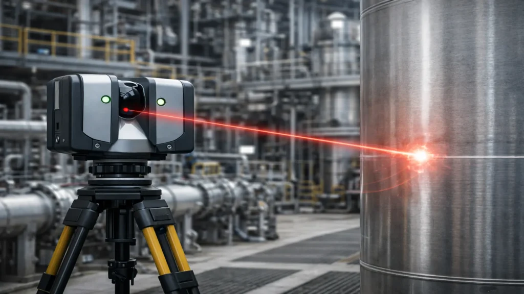
The core of an industrial laser scanner is the Time of Flight (ToF) principle. The equipment emits a laser pulse that travels until it hits a surface and returns to the sensor. Knowing the constant speed of light, the device calculates the exact distance by measuring the time elapsed between emission and reception. This cycle repeats up to two million times per second while the scanner head rotates, sweeping the environment in 360 degrees.
LiDAR scanning applied to industrial plants
Unlike conventional sensors, industrial LiDAR scanning is designed to operate in hostile environments. Its penetration and filtering capability allows capturing complex geometries, such as dense pipe racks or lattice structures, with reliability that passive optical methods (such as photogrammetry) cannot match under variable lighting conditions or metallic surfaces.
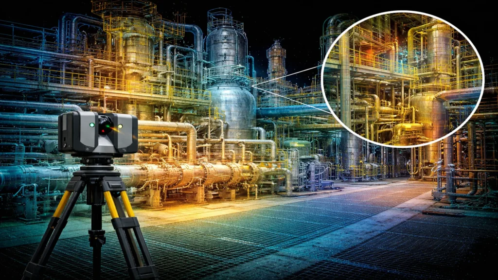
Generation and characteristics of the point cloud
The primary result of this technology is the point cloud. This is a massive set of millions of spatial coordinates (X,Y,Z) that together form a digital skin of the asset.
- Accuracy, resolution, and range: High-end equipment offers accuracies of ±1 mm. Resolution can be adjusted according to need—from coarse grains for general volumes to extreme densities for inspecting flanges or bolts.
- Data management and cleaning: Specialized software filters “noise” (dust vortices, vapor, or moving personnel) to deliver a clean model ready for the engineering phase.
Workflow: From scanning to BIM from the point cloud
Once physical reality has been captured, the next critical step is transforming that raw data into intelligent information.
This is where the Scan-to-BIM process becomes the gold standard for multidisciplinary planning.
Registration and alignment of scans
Since a plant cannot be captured from a single position, multiple scans are required. Registration is the process of stitching individual point clouds together into a single global coordinate system. Reference targets or geometric matching algorithms (Cloud-to-Cloud) are used to ensure that the entire model remains coherent and precise across its full extent.
Converting point clouds into intelligent models
Scan-to-BIM is not simply drawing over the cloud. It is the parametric reconstruction of assets. Instead of seeing “points,” the engineer interacts with digital objects that possess intelligence:
- Pipe and structure extraction: Software detects cylinders and steel profiles, converting them into solid elements with real diameters and thicknesses.
- Metadata linking: Each modeled valve or pump is assigned technical information (material, design pressure, last inspection date), creating the embryo of the Digital Twin.
3D Laser Scanning in turnaround planning?
The true power of 3D Laser Scanning lies not only in capturing data but in transforming decision-making before the first worker enters the plant. During the pre-shutdown phase, the model derived from the point cloud becomes the ultimate testing laboratory.
3D model for early clash detection
Automated clash detection identifies spatial interferences between new design and existing infrastructure. By overlaying the engineering model (CAD) onto the reality capture, the software highlights in red any point where a pipe, support, or cable tray collides with physical reality. Resolving these conflicts in the office saves thousands of dollars in unplanned shutdowns.
Precise prefabrication and lifting simulations
Thanks to the precision of LiDAR scanning, pipe spools can be manufactured in the workshop with the certainty that they will fit correctly the first time (First Time Right).
- Flange validation: Rotation and parallelism of existing flanges are verified for perfect alignment.
- Lifting simulation: It is possible to simulate the trajectory of a crane and the critical load through dense structures, ensuring sufficient clearances for collision-free installation.
Clash detection and CapEx risk mitigation
In capital expansion projects (CapEx), where new units are integrated into already congested spaces, clash detection becomes mandatory.
The ability to validate installations in complex environments drastically reduces forced field adjustments, which are the primary cause of cost overruns in industrial projects.
Impact of 3D Laser Scanning on operational safety
Safety is the pillar of any Turnaround. 3D Laser Scanning directly contributes to the goal of “Zero Accidents” by reducing personnel exposure.
Reducing human exposure through remote capture
The use of long-range LiDAR scanning allows surveying elevated racks or areas with chemical hazards without technicians needing to climb scaffolding or enter controlled atmospheres. If the sensor can see the object, it can measure it.
Technical validation and safety with TEAM Inc.
The application of 3D Laser Scanning in tank inspection under API 653 standards has transformed integrity management. In a recent interview for Inspenet TV at the AMPP 2025 conference, Andy Shingledecker of TEAM Inc. confirmed how prior digital recording acts as the “black box” of an industrial asset.

From digital records to emergency response
The value of reality capture becomes evident in critical situations. TEAM Inc., a pioneer in the commercial standardization of LiDAR scanning, documented a case where a poorly installed valve caused the structural implosion of a tank during draining. Because a scan existed prior to the incident, engineers were able to:
- Differential comparison: Compare the “healthy” state versus the damaged state to map millimetric deformations.
- Repair simulation: Determine the feasibility of returning the tank to service without costly exploratory dismantling.
Operational safety and Remote Visual Inspection (RVI)
A key point highlighted in the interview is the use of scanning to minimize human risk. Under the principle “wherever exposure can be avoided, it should be avoided,” the use of 3D Laser Scanning and robotic systems in confined spaces allows obtaining high-precision data without entering hazardous atmospheres.
In this context, Remote Visual Inspection (RVI) becomes a strategic complement, integrating specialized cameras, robotic devices, and remote access platforms to expand visual and dimensional evaluation capabilities in tanks, pipelines, and pressure vessels.
The convergence of 3D Laser Scanning and RVI not only reduces exposure to physical and chemical risks but also improves the technical traceability of inspections, ensuring regulatory compliance and generating verifiable digital evidence. This methodology provides a level of data density and documentation that traditional methods rarely achieve.
Regulations and global requirements
The adoption of 3D Laser Scanning is not merely a process improvement; it has become a compliance method for international safety and integrity standards.
Mechanical integrity standards
The use of point clouds has become the de facto standard for satisfying audits of:
- API 653 / 570 / 510: Enables analysis of verticality, roundness, and structural deformation in tanks and vessels with full coverage.
- ASME B31.3: Ensures piping installation respects dimensional tolerances, preventing mechanical stresses due to misalignment.
- Additionally, the evolution of 3D Laser Scanning and LiDAR technologies is supported academically by research universities such as the University of South Florida (USF), where the Access 3D Lab develops educational and applied research initiatives in the capture, processing, and analysis of three-dimensional data for infrastructure and industrial environments.
Digital management framework (ISO 19650)
The ISO 19650 standard regulates the Scan-to-BIM workflow. It defines how to capture, organize, and transmit technical information so that the As-built becomes legally traceable and compatible with Common Data Environments (CDE) throughout the asset lifecycle.
Government requirements (BIM Mandate)
Globally, the transition toward reality capture is driven by government mandates focused on operational safety, the creation of Digital Twins for critical infrastructure, and the generation of immutable legal evidence for audits.
Economic impact and return on investment (ROI)
Investing in 3D Laser Scanning is not an extra cost; it is a direct saving in shutdown OPEX.
- Rework reduction: This technology reduces installation errors by an estimated 90%.
- Critical path optimization: By eliminating field adjustments, shutdowns finish on schedule, avoiding penalties and maximizing production.
Conclusions
3D Laser Scanning has ceased to be a competitive advantage and has become a mandatory standard in complex industrial planning. The ability to manage a reliable point cloud ensures that clash detection and the Scan-to-BIM workflow enable plant shutdowns with controlled risks and predictable schedules.
In a market that demands maximum operational efficiency, digitalization through reality capture is the only path toward excellence and sustainability in the era of Digital Twins.
At Inspenet, we lead this technical analysis to transform industrial operations. We also lead the technical and strategic analysis of global energy challenges, promoting specialized content that integrates innovation, sustainability, and resilience to transform industrial operations.
Would you like to deepen the digitalization of your assets?
Explore our technical library or connect with our community of experts to anticipate the challenges of your next plant shutdown. Precision is not optional; it is the standard of modern engineering.
Referencias
- API. API Standard 653: Tank Inspection, Repair, Alteration, and Reconstruction. American Petroleum Institute.
- API. API 570: Piping Inspection Code: In-service Inspection, Rating, Repair, and Alteration of Piping Systems. American Petroleum Institute.
- ASME. Boiler and Pressure Vessel Code (BPVC), Section VIII & Section IX: Rules for Construction of Pressure Vessels and Welding Qualifications. American Society of Mechanical Engineers.
- ASME. B31.3: Process Piping Guide. American Society of Mechanical Engineers.
- ISO. ISO 19650: Organization and digitization of information about buildings and civil engineering works, including building information modelling (BIM). International Organization for Standardization.
- ASTM International. ASTM E2544: Standard Terminology for Three-Dimensional (3D) Imaging Systems. ASTM International.
- ASTM International. ASTM E57.02: 3D Imaging Systems – Test Methods for Evaluating Laser Sensors. ASTM International.
- OSHA. Safety and Health Topics: Confined Spaces. Occupational Safety and Health Administration.
- Video de Inspenet TV. “TEAM Inc.” impulsa la inspección industrial mediante Escaneo Láser 3D y Gemelos Digitales. Entrevista a Andy Shingledecker en AMPP 2025.
Frequently Asked Questions (FAQs)
What accuracy does 3D laser scanning offer?
The standard accuracy in industrial environments ranges between ±1 mm and ±3 mm, depending on the equipment used and the scanning distance.
What is a point cloud and how is it used in engineering?
A point cloud is a collection of millions of spatial coordinates that represent the physical surface of an asset. It serves as the foundation for Scan-to-BIM modeling and engineering simulations.
How does LiDAR scanning work?
LiDAR scanning uses laser light pulses to measure distances through the Time of Flight (ToF) principle, making it ideal for capturing dense geometries in highly congested industrial plants.
What is the difference between 3D laser scanning and Scan-to-BIM?
3D laser scanning refers to the capture of raw spatial data, while Scan-to-BIM is the process of converting that data into intelligent and parametric 3D models.
How does clash detection help in a Turnaround?
Clash detection identifies spatial conflicts before execution, eliminating rework and forced adjustments along the project’s critical path.