Table of Contents
- Foundations of Power Piping design
- Fundamental Differences: B31.1 vs. B31.3
- Fabrication and Assembly: Precision in Shop and Field
- Inspection and testing: The rigor of chapter VI
- Digital transformation: Traceability and asset management
- The future: Operation, maintenance, and updates
- Conclusions
- References
- FAQ Questions about ASME B31.1
ASME B31.1 defines how piping for power service in the thermal energy industry must be designed and verified. Its piping design requirements, covering materials, thicknesses, joints, testing, and stress limits, reduce the risk of leaks or ruptures when operating with high-pressure, high-temperature steam and feedwater.
In power plants, applying this code at every stage of the life cycle, from engineering to in-service inspection, enhances reliability and reduces unscheduled downtime. Understanding the differences between B31.1 and B31.3 also guides the selection of the appropriate code based on the fluid and criticality, protecting both assets and personnel.
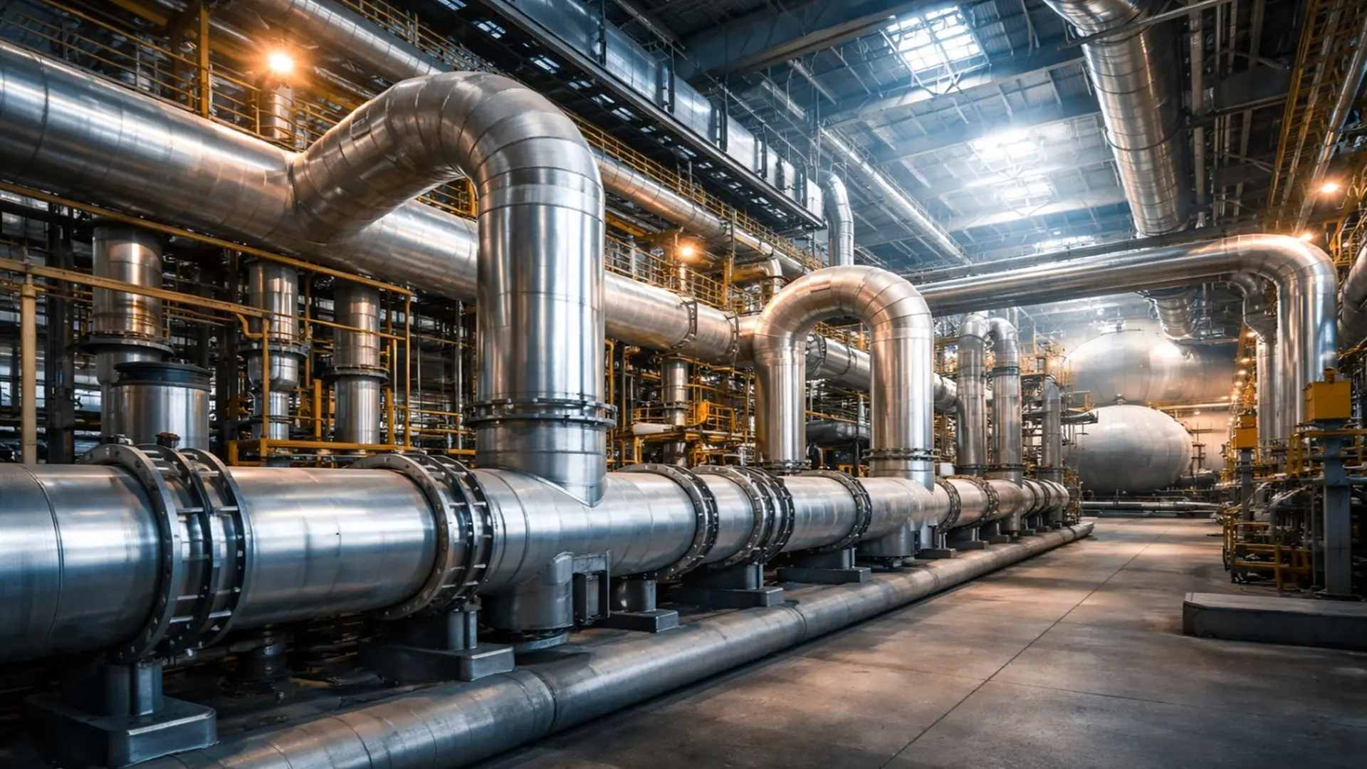
Foundations of Power Piping design
A main steam line does not fail due to “bad luck”: it fails because of accumulated stresses, poorly managed thermal expansion, or weld discontinuities that no one detected in time. ASME B31.1 exists so that these risks are designed for, controlled, and inspected using a methodical approach within the generation industry, where operating conditions demand real technical margins.
In power plants, the design of piping systems is not limited to simply tracing routes. It is an exercise in mechanical resistance and deformation control against internal pressure, external loads, vibration, transients, and thermal effects. Under ASME B31.1, the engineer must evaluate not only the design pressure but also dynamic forces, start/stop cycles, and differential expansion, as these are typically where high-consequence failures originate.
1. Critical Variables: Pressure and Temperature
Unlike other services, in power plants, temperature can dictate material selection just as much as pressure. When steam operates in elevated ranges (above 427°C, depending on the material and condition), carbon steel progressively loses its mechanical properties, and the phenomenon of creep becomes dominant: a time-dependent permanent deformation under sustained load at high temperatures.
In these cases, alloys such as chromium-molybdenum come into play, offering better resistance to creep and damage from prolonged exposure. The key is to understand that integrity does not just depend on “withstanding the pressure,” but on sustaining mechanical performance throughout years of severe thermal service.
2. Flexibility and Support: Expansion is also a Load
A power piping system must be able to “move” in a controlled manner. Main steam lines can expand several centimeters during start-ups and load changes. If the design does not incorporate sufficient flexibility (expansion loops, appropriate geometries) and a correct philosophy of supports, guides, and variable load hangers, that expansion transforms into loads on nozzles, flanges, and welds.
The typical result of a rigid system is not immediate but is predictable: stress concentration, thermal fatigue, and progressive damage at critical points near the boiler and turbine, leading to costly forced outages and increased operational risk.
Fundamental Differences: B31.1 vs. B31.3
In the thermal energy industry, doubts frequently arise regarding which code to apply when steam lines and services coexist within complex facilities. Although both belong to the ASME family, their safety philosophies and design criteria respond to distinct operational risks. Choosing correctly is not merely a documentation detail: it defines allowable stresses, manufacturing controls, and inspection requirements.
- Scope and application: ASME B31.1 is oriented toward piping for power service: systems associated with generation, boilers, steam, and feedwater, where accumulated energy and thermal cycles dominate the risk. Conversely, ASME B31.3 specializes in process piping for refineries and chemical plants, where the variety of fluids, toxicity, and chemical corrosion are the dominant challenges.
- Allowable stresses and safety factors: A relevant technical difference appears in the allowable stresses and the approach to risk. The B31.1 standard tends to be more conservative for typical power services because a failure in high-pressure steam can have violent and far-reaching mechanical consequences. In B31.3, the focus adapts strongly to the nature of the fluid and the process context (hazard, corrosion, release) compared to leaks in a standard process line.
- Rule of thumb: decide by function, not location: The most common mistake is choosing the code based on “where” the piping is located in the plant rather than “what it does.” If the system produces or transports steam/feedwater for generation or critical power services, the reference framework is usually B31.1, even if the facility is a refinery. Confusing these boundaries can lead to undersized solutions against thermal cycles and expansion, compromising long-term performance.
In the field, the “B31.1 vs. B31.3” dilemma is resolved faster by deciding based on the system’s function rather than its plant location. The following table summarizes practical criteria for code selection to avoid undersizing or insufficient controls.
Application comparison table
| Criterion | ASME B31.1 (Power Piping) | ASME B31.3 (Process Piping) |
| Typical use | Steam/feedwater and power services in generation. | Process piping in refineries and chemical plants. |
| Dominant risk | High energy + thermal cycles/transients. | Fluid (toxicity), corrosion, and chemical compatibility. |
| Philosophy | Control of thermal loads and mechanical integrity in power. | Management of process and fluid hazards. |
| Correct decision | Based on system function, not location. | Based on process function and fluid nature. |
| Common error | Choosing B31.3 just for being “in a refinery.” | Choosing B31.1 just for “having steam.” |
| Rule of thumb | Generation/critical service → B31.1 | Process fluid → B31.3 |
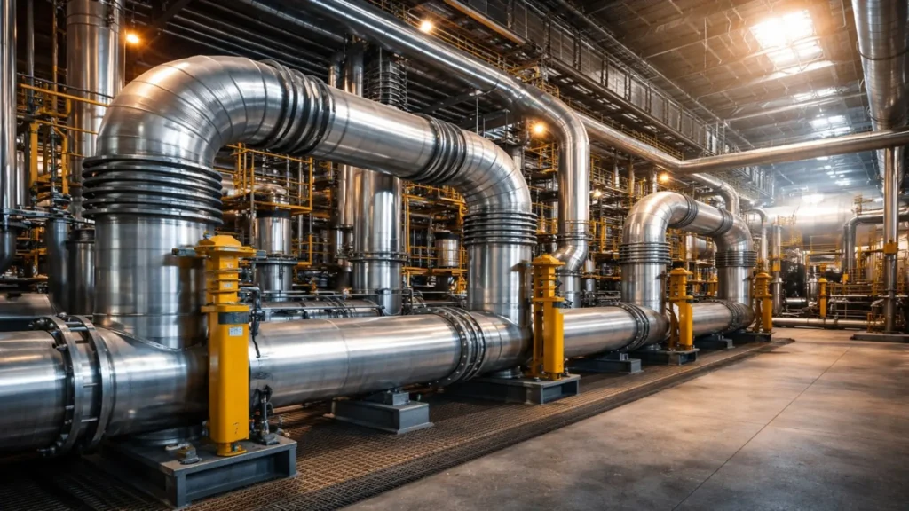
Fabrication and Assembly: Precision in Shop and Field
From this point forward, compliance ceases to be just engineering and becomes execution control. In B31.1, fabrication is not merely “joining parts”: it is about preserving metallurgical properties, controlling discontinuities, and ensuring traceability. Anything not executed well in the shop or field eventually appears in service as a leak, crack, or deformation.
Welding and qualification
Every welded joint in power systems must be performed by personnel qualified under ASME Section IX, using consistent and controlled procedures. Since these lines experience heating and cooling cycles, metallurgical quality matters as much as geometry: lack of fusion, porosity, or inclusions become stress concentrators that evolve into thermal fatigue cracks.
Post-weld heat treatment (PWHT)
One of the most critical points in chromium-molybdenum alloys is stress relief. During welding, the heat-affected zone may be left with microstructures and residual stresses that increase susceptibility to cracking and premature failure. PWHT (performed with controlled parameters) reduces internal stresses and stabilizes metallurgical conditions. Omitting it or executing it poorly is a direct shortcut to accelerated degradation in service and a leading cause of premature failure in the power industry.
Bending and tolerances
Bending alters the thickness of the outer wall and can ovalize the pipe. Therefore, the code establishes limits and acceptance criteria: the manufacturer must guarantee that the remaining thickness and resulting geometry are sufficient for the design pressure and to maintain flow integrity. In power generation, where thermal margins are narrow, small deviations are paid for dearly over time.
Key fabrication and assembly controls
- Materials and traceability (MTR / Heat number): Verifying that every section, fitting, and component matches its certificate prevents installing incorrect materials in high-temperature services.
- Positive material identification (PMI): Field confirmation of alloys (e.g., Cr-Mo) when there is a risk of mix-ups; reduces critical errors from involuntary substitution.
- Joint preparation (Beveling and Fit-up): Control of bevel, root gap, and alignment before welding; prevents lack of penetration, internal misalignment, and stress concentrators.
- Dimensional control of spools and flanges: Parallelism, orientation, and coaxiality; minimizes leaks and parasitic loads that later punish supports, nozzles, and equipment.
- Consumables and welding parameters: Handling of electrodes/wires (humidity/oven), gas, and WPS compliance directly impacts defects and performance under thermal cycles.
- Supports and hangers (Cold/Hot adjustment): Installation and calibration (setting) of spring hangers, guides, and anchors; incorrect adjustment turns thermal expansion into a load on welds and nozzles.
- Internal cleaning and preservation: Removal of slag/burrs, flushing/blow according to the system, and sealing ends; protects valves, instrumentation, and turbines before startup.
- As-built and weld maps: Record of welds, PWHT, NDE, and field changes; enables auditing, traceability, and reliable maintenance.
Inspection and testing: The rigor of chapter VI
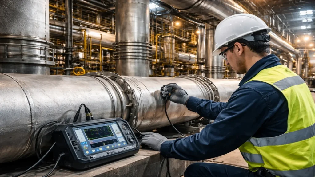
Chapter VI of the standard defines who, how, and when the quality of the work must be validated. In power piping systems, inspection is not a suggestion: it is part of the quality control required to release the system for testing and commissioning, with clear traceability from materials to the final test.
Inspector responsibilities
The standard clearly distinguishes between the manufacturer’s inspection and the owner’s inspection. The latter typically involves authorized personnel who verify compliance in material reception, procedure control, PWHT records, NDE, and the final test. This separation avoids conflicts of interest and strengthens documentation control until the final hydrostatic test complies with ASME B31.1.
Non-destructive examination (NDE) methods
Depending on the severity of the service, the code requires various levels of examination:
- Visual (VT): The first barrier to detect surface discontinuities and general condition.
- Ultrasonic (UT) and Radiography (RT): Volumetric techniques to detect internal weld discontinuities.
- Magnetic Particle (MT) or Dye Penetrant (PT): For the detection of fine surface cracks (depending on material and accessibility) that the human eye cannot perceive.
The hydrostatic test acts as the final verification: the system is subjected to a pressure higher than the operating pressure to demonstrate mechanical robustness before exposing it to actual steam.
Digital transformation: Traceability and asset management
Today, complying with ASME B31.1 is not limited to inspecting “when it’s time.” The challenge in plants with thousands of meters of line is converting inspections and documents into useful information: knowing which joint was welded with which procedure, what PWHT was applied, what NDE was executed, and how thickness or damage evolves over time.
Digitalization has allowed the thermal energy industry to move from reactive maintenance to a proactive integrity strategy. Examples of applications and solutions include:
Centralization with AsInt’s IntelliSuite
Total traceability is a challenge in plants with a high volume of joints and spools. Platforms like IntelliSuite (AsInt) allow for the centralization of design, fabrication, and inspection data in a single repository, facilitating quick audits of minimum thicknesses, PWHT records, NDE evidence, and testing status.
Field precision with Eddyfi Technologies
To feed any platform with useful data, field capture must be consistent. Inspection solutions, such as equipment and scanners from Eddyfi Technologies, provide repeatable measurements to detect and size damage mechanisms, such as corrosion under insulation or indications associated with thermal fatigue, optimizing decision-making.
In this sense, Eddyfi’s Capture 5.0 technology stands out for its ability to simplify complex ultrasonic processes, allowing for faster and more precise data interpretation for compliance with international standards.
To learn more about this technology, we recommend watching the technical talk “The Evolution of Ultrasound“. Interview on Capture 5.0 on Inspenet TV.

The future: Operation, maintenance, and updates
The regulation is not a static document. Chapter VII of ASME B31.1, focused on operation and maintenance, reinforces a paradigm shift: it is no longer enough to build well; one must demonstrate that the system remains fit for service through inspection, evaluation, and continuous monitoring programs.
For professionals who wish to stay up to date with code changes, monitoring technologies, and new inspection practices, technical congresses such as POWERGEN International 2026 (San Antonio, Texas: January 20–22, 2026, Henry B. Gonzalez Convention Center) are relevant spaces for updates.
Conclusions
Guaranteeing the integrity of power piping is a continuous commitment to safety and efficiency. From piping design to in-service inspection years later, ASME B31.1 acts as the technical roadmap to reduce high-consequence failures in power plants. When regulatory rigor is combined with digital traceability and high-quality NDE, operation gains reliability, unscheduled downtime is reduced, and the useful life of critical assets is extended without compromising safety.
From the perspective of Inspenet, ASME B31.1 is not just a code: it is a practical guide to designing and inspecting safely, protecting critical assets, and reducing outages in power plants. As a professional connection platform and media partner of API, we continue to train and update the community with real sector trends, including the most relevant information presented in forums like POWERGEN 2026.
References
- American Society of Mechanical Engineers. (2024). Power piping (ASME B31.1-2024).
- American Society of Mechanical Engineers. (2024). Process piping (ASME B31.3-2024).
- American Society of Mechanical Engineers. (2025). BPVC Section IX: Welding, brazing, and fusing qualifications.
- International Organization for Standardization. (2021). Non-destructive testing—Qualification and certification of NDT personnel (ISO 9712:2021).
- Peng, L.-C., & Peng, T.-L. (2009). Pipe stress engineering.
- POWERGEN. Event information: POWERGEN 2026.
FAQ Questions about ASME B31.1
When should ASME B31.1 or B31.3 be applied?
ASME B31.1 typically applies to power piping associated with power generation and critical services, such as steam and feedwater, where thermal cycles and high stored energy dominate. In contrast, ASME B31.3 is used for process piping (refineries and chemical plants), where risk depends primarily on the conveyed fluid. The practical rule is to decide based on system function, not location.
What are the key factors in piping design?
Under ASME B31.1, critical factors usually include pressure and temperature, material selection, minimum thickness, joints, and testing. In power plants, thermal expansion due to startups and shutdowns is also dominant, so flexibility, supports, guides, and anchors are evaluated. Good piping design controls mechanical and thermal loads to reduce leaks, deformation, and long-term thermal fatigue.
Why does thermal expansion cause failures?
When heated, piping tends to elongate and displace by several centimeters. If the system lacks sufficient flexibility, this expansion is transferred as loads to nozzles, flanges, welds, and supports. In power plants, repeated startup and load-change cycles accumulate stresses, potentially leading to thermal fatigue, recurrent leaks, or damage at boiler and turbine interfaces.
What are the most critical fabrication controls?
Beyond qualifying welders and procedures, key controls include material traceability, PMI for alloys, joint preparation (fit-up), dimensional control of spools and flanges, and proper execution of PWHT when applicable. In the thermal power industry, these controls reduce metallurgical defects and installation errors that often appear in service as cracks, leaks, or deformation in power piping.
Which NDT methods are most commonly used in power piping?
The most common are VT to check surface condition and general integrity; UT or RT to detect internal weld discontinuities; and MT or PT to locate fine surface cracks, depending on material and accessibility. Selection depends on criticality and project requirements. Before commissioning in power plants, hydrostatic testing validates the system’s mechanical strength above its operating pressure.
Is there digital traceability for ASME B31.1?
Digital traceability centralizes design, fabrication, PWHT, NDT, and testing records into a searchable history. This streamlines compliance audits and improves integrity decisions during service. In the thermal power industry, it also helps link measurements to specific joints and components in power piping, supporting more proactive strategies and reducing unplanned outages in power plants.