In the industrial field, the flange adjustment on piping and equipment is an essential component to ensure the efficiency and safety of systems such as: chemical processing plants, refineries, water treatment facilities, and oil and gas distribution systems. Properly fitted flanges are critical to prevent leaks and maintain structural integrity, avoiding costly downtime and safety risks.
In the industrial environment, flange adjustment on pipelines and equipment is an essential component to ensuring the efficiency and safety of systems such as: chemical processing plants, refineries, water treatment facilities, and oil and gas distribution systems. Properly tightened flanges are critical to prevent leaks and maintain structural integrity, avoiding costly downtime and safety risks.
A considerable aspect of this process is the correct application of torque, for which the bolt torque chart becomes an indispensable tool. This article will explore in detail the fundamentals of flange tightening, providing a practical and detailed guide to ensure that each tightening is accurate and effective. Discovering how to apply the optimum torque, the necessary tools and best practices to maintain the functionality and safety of industrial systems.
Fundamentals of flange adjustment
Industrial flange adjustment is a significant process in the installation and maintenance of piping systems and industrial equipment. It involves applying a specific torque to the flange bolts to ensure a tight and secure joint. The importance of proper torque cannot be underestimated, as under-tightening can result in leaks, while over-tightening can damage flanges or bolts, compromising the integrity of the system.
The term “torque” refers to the rotational force applied to a bolt or nut, usually measured in pound-feet (lb-ft) or newton-metres (Nm). ASME PCC 1 provides specific guidelines on recommended practices for Flange adjustment, ensuring uniformity and safety in installations. Part of these guidelines include the sequence of tightening patterns, which ensures a uniform distribution of load on the flange, minimising the risk of deformation and leakage.
It is important to understand and correctly apply these fundamentals to maintain the operability and safety of industrial systems, avoiding failures and ensuring efficient operations.
Flange adjustment tools
Tightening flanges requires the use of specialist tools to ensure the correct torque is applied. Among the most commonly used tools are torque wrenches, which allow the exact torque required to be measured and applied. There are several types of torque wrenches, including click, electronic and dial torque wrenches, each suitable for different applications and levels of accuracy.
For flange tightening, in addition to torque spanners, other devices such as torque spanners and torque multipliers are used, which are essential for tightening large bolts that require high levels of torque. These tools ensure that torque is applied in a uniform and controlled manner, preventing damage to flanges and bolts.
It is essential that all torque measurement tools are correctly calibrated and maintained. Regular calibration ensures measurement accuracy, while proper maintenance prolongs service life and ensures optimum performance. Ignoring these considerations can lead to errors in tightening, with potentially serious consequences for the safety and operability of industrial systems.
Bolt torque chart
The bolt torque chart is an important tool in the flange adjustment on pipelines and industrial equipment. This table provides recommended torque values for different bolt sizes and materials, ensuring that each tightening is made with the accuracy necessary to maintain the integrity of flanged connections. The table generally includes columns specifying bolt diameter, thread pitch, bolt material, and recommended torque, usually expressed in pound-feet (lb-ft) or newton-metres (Nm).
To read and use the bolt torque chart correctly, first identify the diameter and material of the bolt to be tightened, then find the corresponding row in the chart and locate the recommended torque value. It is recommended that this value be followed when applying the torque, using a calibrated torque wrench to ensure accuracy.
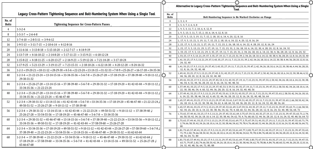
Bolt torque tables can be found in bolt and flange manufacturers’ manuals, industry standards such as ASME (American Society of Mechanical Engineers)1 ( Tabla 1), and industry-specific technical documents. In addition, many suppliers of industrial equipment and components include torque tables in their product catalogues and on their websites.

The importance of following the bolt torque chart recommendations cannot be underestimated. Insufficient torque can result in leaks and improper joints, while excessive tightening can cause deformation or breakage of the bolts, compromising the integrity of the flange. Adhering to the values specified in this table is essential to maintain the safety and efficiency of industrial systems. Therefore, having an up-to-date and reliable torque table is an essential practice for any professional involved in flange adjustment.
Bolt pattern sequence
Which bolt patterns to use for flange tightening?
One of the key elements in achieving an effective seal when tightening a flange is the bolt tightening sequence, which ensures a balanced tension across the gasket. This sequence is important because it controls the stress variation in the flange gasket components2.
It is essential that the gasket is compressed evenly along the flange face, if adjacent bolts are tightened rather than opposite, the compression of the gasket would be uneven, compromising its tightness and possibly damaging it. The flanges should be kept parallel, and the most optimal method is to use a suitable bolt tightening pattern with an initial partial load in a clockwise direction and then gradually increase the load.
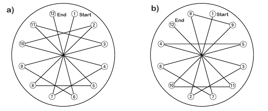
Figure 1, below shows a sequence of 12 bolts in this case the pattern is to always tighten the opposite bolt, e.g. the sequence would be: 1-7-4-10… (Figure 1a), whereas in Figure 1. b) the balancing is done by combining opposite bolts with a slight variation: 1-2-3-4…

Flange adjustment procedure
- Preparation: Before starting, make sure you have all the necessary tools, including calibrated torque wrenches, torque wrenches and the appropriate bolt torque chart.
- Cleaning and alignment: Clean the flange contact surfaces and make sure they are properly aligned. Proper alignment is crucial to avoid undue stresses and leaks.
- Bolt installation: Insert bolts and nuts by hand, making sure they are properly positioned. Do not apply torque at this stage.
- Initial tightening: Apply a light initial torque to each bolt in a cross or star sequence. This ensures that the load is evenly distributed and helps to seat the flange surfaces.
- Tightening pattern sequence: Follow the recommended tightening pattern sequence, gradually increasing the torque in steps. The typical sequence is cross or star, starting with a low torque and increasing in even increments until the value specified in the table is reached.
- Final Check: After applying the final torque, check each bolt again in the same sequence to ensure that there are no changes in torque due to component over-torquing.
Tightening uniformity and leak prevention considerations: It is necessary to maintain tightening uniformity on all bolts to avoid uneven stresses that can cause deformation and leakage. Using calibrated torque wrenches and following recommended tightening pattern sequences ensures uniform load distribution.
Performing periodic flange tightening checks during preventive maintenance is a recommended practice to ensure the continued integrity of flanged joints, guaranteeing safe and efficient tightening of flanges, preserving the functionality and safety of industrial systems.
Application of optimum torque
Optimum torque is the exact amount of rotational force applied to a bolt to ensure a safe and effective flanged joint without compromising the integrity of the material. Determining and applying optimum torque is crucial to maintaining the functionality and safety of industrial systems.
Factors affecting optimum torque: Several factors influence optimum torque. Bolt material is one of the main ones, as different materials have different strength and elastic properties. For example, stainless steel bolts require different torque than carbon steel bolts. Operating conditions, such as temperature and pressure, also play a key role. A high temperature environment can affect the thermal expansion of the bolt and flange, altering the required torque. In addition, the presence of lubricants on the bolt threads can significantly change the torque required to achieve the desired tightening.
Practical examples of calculating optimum torque: Suppose we are tightening a ¾-inch diameter carbon steel bolt in a moderate temperature environment with no lubricant. Using the above table, we identify that the recommended optimum torque is 150 lb-ft. If lubricants are added to the threads, this value may need to be reduced to avoid overtightening, perhaps to 120 lb-ft, to compensate for reduced friction. Making these careful adjustments ensures that the flanged joints maintain their integrity under various operating conditions.
Leak prevention in flanged joints
Leak prevention in flanged joints is critical to the safety and efficiency of industrial systems. Leaks not only represent a loss of product, but can also be dangerous and cause environmental and structural damage.
Importance of Leak Prevention: Leaks can lead to operational inefficiency, additional costs and significant safety risks. In industries that handle hazardous or high-pressure fluids, leak prevention is critical to avoid accidents and ensure compliance with safety regulations.

Strategies and best practices to ensure a tight fit: One of the best practices to prevent leakage is to ensure that the flange contact surfaces are clean and free of imperfections. Using proper torque and following recommended tightening sequences is also crucial. Applying a cross or star sequence helps to distribute the load evenly and avoid leak points.
Use of proper gaskets and seals: Selecting the right gaskets and seals is essential to ensure a tight fit. High quality gaskets that are compatible with the operating conditions of the system (pressure, temperature, fluid type) provide an effective barrier against leakage. Regularly checking the condition of gaskets and replacing them as needed is also a recommended practice to maintain the integrity of flanged joints. Implementing these strategies ensures a safe and efficient system, minimizing the risk of leakage and its associated consequences.
Regulations and standards
When flange adjustment and bolts, adhering to regulations and standards is essential to ensure the safety and efficiency of industrial systems. One of the most relevant standards is ASME PCC 1 (American Society of Mechanical Engineers), which provides detailed guidelines on flange assembly, including recommendations for tightening torque, tightening sequences, and verification procedures. These guidelines ensure that flanged joints are tightened uniformly and securely, minimizing the risk of leakage and structural failure. The importance of following these guidelines lies in the uniformity and consistency they provide.
The standardization of tightening procedures reduces the margin for human error and ensures that all connections meet safety and performance requirements. In addition, compliance with regulations such as ASME PCC 1 is often a legal and certification requirement necessary to operate in many industries. Adopting these practices not only protects the integrity of systems, but also ensures the safety of workers and the environment.
Answers to frequently asked questions
How do I know what torque to apply to a bolt?
Determining the proper torque for a bolt requires consideration of several key factors. First, the bolt and flange material must be known, as different materials have different strength limits. Operating conditions, such as temperature and system pressure, also affect the torque required. In addition, the presence of lubricants on the threads can change the coefficient of friction, altering the required torque.
Conclusions
Proper flange adjustment in piping and industrial equipment is necessary to ensure the safety, efficiency and operability of the systems, according to regulations and standards such as ASME PCC 1. The bolt torque table has been presented as an indispensable tool to ensure the correct application of torque, avoiding both leaks and structural damage.
The detailed procedure for Flange adjustment, from preparation and cleaning to final verification, provides a practical guide to ensure a uniform and safe tightening. As well as, the application of optimum torque and leakage prevention strategies are significant in the integrity of flanged joints under operating conditions.
Industry professionals must follow proper tightening practices to protect industrial systems from failure, ensure a safe working environment and comply with applicable regulations. Using resources such as torque tables and standards manuals is essential to make accurate adjustments; adopting these practices ensures the service life and reliability of industrial installations.
References
- ASME PCC-1-2019 (Revisión de ASME PCC-1-2013) Pautas para el ensamblaje de bridas atornilladas en el límite de presión.
- https://ktnvalves.com/es/como-apretar-una-brida-correctamente/

