
CUPS Problem
Corrosion under pipe support (CUPS) is a challenging issue faced by the oil and gas industry because it presents a particular threat to pipework integrity and life extension on aged plants. This is because of the local deterioration, coupled with difficulties of inspection to determine the actual pipe condition. Failure of these pipes caused by CUPS can potentially lead to a major loss in containment, as it is difficult to repair the pipe online and the disruption can be significant in terms of cost and safety.
Since CUPS are generally external corrosion between 4 to 8 o’clock of the pipe at pipe supports, then detecting the location of CUPS is not a major challenge. However, the biggest challenge is to determine the size of this corrosion in order to asses the structural integrity of the pipe. Existing methods of CUPS inspection, such as MRUT, may be able to detect CUPS, but are unable to size the extent of the corrosion accurately.
GUL Scanning
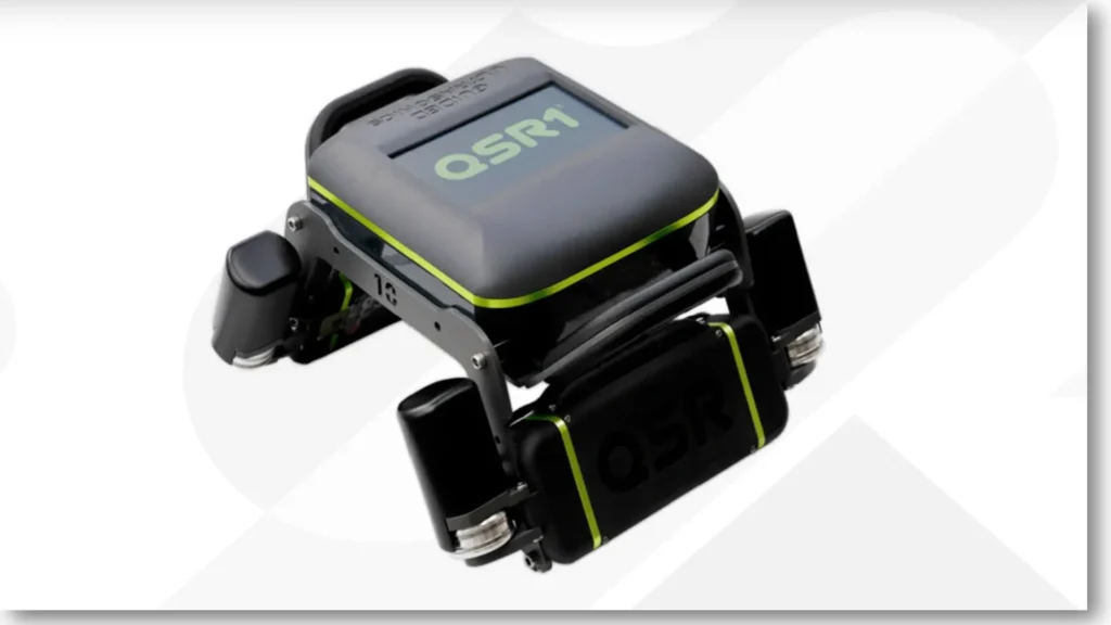
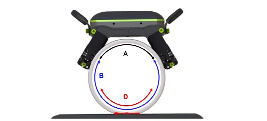
The QSR1 is GUL’s guided wave scanner that accurately detects and size corrosion under simple pipe supports. By using a combination of circumferential guided waves and a novel frequency analysis method, the QSR1 gives operators the accurate measurements of the remaining pipe wall thickness. The QSR1® will semi-automatically scan along the pipe to produce an easy-to-understand graph, which plots the minimum wall thickness against its axial position along the pipe.
GUL Scanning of Simple Support with CUPS
WaveProQSR Results
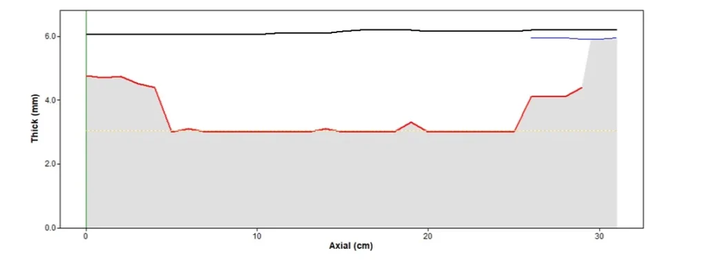
In this case study, the QSR1® was used on a NPS 12 Schedule 20 pipe resting on a simple support. The QSR1® scan results presented two key findings. Firstly, touch point corrosion at the pipe resting at the simple support was confidently detected and visually verified by operators; as shown in the image from the first page. Secondly, the maximum wall loss measured was 3.00 mm or 50% maximum wall loss for this pipe. The inspection team followed up from the QSR1® results by lifting the pipe to directly measure the depth and extent of the corrosion using a meter rule, as shown in the first figure. This successfully verified the accuracy of the QSR1® at detection and sizing of the corrosion under pipe support, which helped to prevent a potentially hazardous incident on site. In conclusion, the QSR1® successfully detected and provided corrosion sizing measurements that enable asset managers to confidently make structural integrity and operational decisions.
Reference
- GUIDED ULTRASONICS LIMITED; GUL. Simple Support Corrosion Sizing; Accessed August 12, 2024. https://www.guided-ultrasonics.com/wp-content/uploads/2023/03/QSR1_CaseStudy1_rev0c-A4.pdf?