

This article presents a proposal to be considered, to move from a routine of periodic regulatory inspections and a traditional operational control focused on the assurance of the required steam production, based on the Condition Assessment methodology, through the analysis of the possible and credible damage mechanisms in each boiler component, which allows defining short and medium term Inspection and Maintenance Plans, and include in the operational routines temperature and combustion condition measurements, which in real time generate accurate and immediate corrective actions, in addition to information that feeds the inspection plan, to comprehensively optimize efficiency, availability and Maintenance Management, ensuring the Condition, Reliability, Operational Health and Safety of the Boilers.
Situation analysis
Boiler maintenance, in many industries and steam thermal power plants, where boilers are essential equipment for production and/or generation, is usually of the Reactive (corrective) type or a variant thereof, even in installations where Proactive Maintenance or Reliability Centered Maintenance is applied to Rotating Equipment (Turbine, Fans and Pumps).
Boiler maintenance planning is usually based on a list of the most recent and frequent failures, despite the fact that, depending on their operating times, conditions and operational regimes, a certain variety of damage mechanisms are generated and evolve, which are not always evident upon visual inspection.
Criteria for the definition of inspection plans
When talking about boiler reliability, the owner or user of this equipment is sometimes limited to what is required by the Safety Regulations of the Jurisdiction in which the boiler is installed. Regulatory requirements such as Periodic Control Inspections focus on visual inspection, hydrostatic testing, verification of pressure relief valve actuation (safety) and in some countries the evaluation of control and safety system alarms and trips.
In certain regulations, indications are given to make a condition assessment, using non-destructive testing or supplementary testing, after a certain period of time. In Spain, Royal Decree 2060/2008 of December 12, 2008 and its Complementary Technical Instructions (under revision and at the time of writing this article is in a period of allegations) give indications such as:
When the visual inspection and the operating history of the boilers show irregularities and there are indications to suspect that in any part, element or component of the boiler there may be important defects, supplementary tests must be carried out, which the person responsible for the inspection by the Inspection Agency or Authorized Control Body must agree with the user or with the technician designated by the user (1).
Normally, when it is proposed to carry out an “inspection plan” or to perform supplementary tests on a boiler, it is observed that a thickness mapping is developed, thus assuming as the only evaluation criterion the erosion and/or corrosion wear of all boiler components, without considering possible mechanical and/or aging damage mechanisms, which normally do not show thickness losses; or inspections are carried out whose focus or scope is limited to the areas of the boilers that have shown recent and repetitive failures.
Effect of operating conditions on integrity and reliability availability and use of temperature measurements
Boilers due to their operational cycling condition, due to requirements of the electrical network for generation plants or due to work shifts or production plans in the industry in general; due to the use of fuels out of specification, seeking to reduce production costs or using those found in the market, which produce irregularities in combustion conditions, thermal balances and general behavior of the boiler; besides observing acceleration of corrosion and erosion damages, the boilers enter into conditions that favor the preferential development of damage mechanisms such as mechanical and/or thermal fatigue, aging or thermal degradation of different types, among others, and none of them are detectable by taking thickness measurements. These conditions are not always prevented and become a problem of loss of reliability, availability and even security.
In the normal and/or routine operation of boilers, operators basically keep track of the production parameters: fuel, water and steam flow, their temperatures and pressures, and additionally monitor the water level inside the boiler and in larger capacity boilers that operate at higher pressure, they verify the opening percentages or consumption of tempering water and temperatures in the lower and upper part of the upper dome, because this is established in the manufacturer’s manual or operating procedures.
These parameters are considered sufficient to monitor the boiler, but in addition to these, in many cases boilers have temperature measurements of both fluids (gases, water and/or steam) in several of its passages, as well as tube skin and/or essential components, which provide information on irregular operating conditions and boiler inefficiency that could and should be corrected immediately, but in many installations these temperatures are not monitored.
It is very convenient to monitor, control, record and analyze these temperatures, which are seldom taken advantage of, as they make it possible to visualize over time, by evaluating trends, whether a specific damage mechanism may be occurring prematurely in one of the boiler components.
If they were used in real time and analyzed not only at the time of remaining life studies, when the boiler is already 20 or 30 years old, during routine operation it would be possible to correct trends and irregular operating conditions, maintain optimum efficiency, ensure reliability, prevent degradation and/or unexpected failures with unscheduled shutdowns, meet the life expectancy of the various boiler components and even optimize boiler safety.
Inspection plans based on possible damage mechanisms
In addition, when defining an inspection plan, based on methodologies equivalent to “Condition AssessmentThe EPRI’s “Condition Assessment”, to determine the actual state of integrity and reliability of the boiler, in search of the presence and degree of evolution of the various probable damage mechanisms in the different critical components, knowing the relationship between the temperatures mentioned above, in the different operating conditions (start-ups, shutdowns, during load variations, etc.) and these mechanisms, it is very convenient and practical to expand the operational parameters to be monitored and regulated, including temperature values that are often measured but not used as routine monitoring parameters.) and these mechanisms, it is very convenient and practical to expand the operational parameters to be monitored and regulated, including temperature values that are often measured but not used as routine monitoring parameters.
Some of the damage mechanisms that should be considered in the different components of the boiler and that influence unforeseen failures and remaining service life, could be:
- Thermal creep (Creep), Softening (Spheroidization), Strain aging,
- Decarburization, Carburization,
- Rapid overheating,
- Transformation by quenching (tempering),
- Mechanical fatigue,
- Thermal fatigue,
- Erosion,
- Corrosion (local or general)
- Water-steam side,
- Flue gas side (hot side and cold side),
- Low thermal insulation,
- Corrosion under deposits
- Hydrogen damage,
- Fatigue corrosion,
- Stress corrosion,
- Sensitization in case of stainless steel,
- Caustic fragilization,
- Corrosion – Erosion
It should be emphasized in the definition of the Inspection Plan with supplementary tests (which components to inspect, which mechanisms to look for and which non-destructive tests to use), that there are very few damage mechanisms that can be determined using only visual inspection and thickness measurements.
More than one inspection technique can be used to detect and characterize a specific damage mechanism. Likewise, a single inspection technique may be able to detect and characterize several types of damage mechanisms, but no single technique is able to detect and characterize all damage mechanisms.
In order to carry out such a supplementary test plan by making a prior evaluation of the boilers’ operating history, it is necessary in a first stage to First Phase survey and evaluate information related to the boiler’s original manufacturing design; years of service; design variations; operating conditions and habits that deviate the boiler from the manufacturer’s recommended procedures and best practices; parameter records and operational regime or cycling (“See Figure 1”); out-of-service periods and controls on preservation methods, chemical control history (“See Figure 2”); previous inspections, examinations and tests; validation of damage mechanisms and analysis of the causes of failures already observed in previous years, in the various components of the boiler (“See Figure 3”); repairs (definitive and temporary) and alterations.
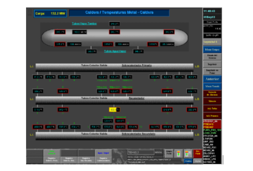
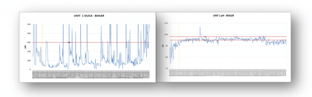
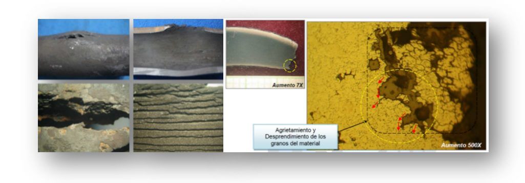
Figure 3. Particular case of damage mechanisms reported in boiler components.
It is considered important, from the operational point of view, for the evaluation of trends in the efficiency or performance of the boilers, the monitoring of fluid temperatures (flue gas, water or steam) at different loads or conditions of the boiler, following the manufacturer’s operation and maintenance manual, but it should be considered very important for the operator to be aware of the correlation of these measurements and the temperatures of the metals in the various components and in other cases directly the measurements of the tube metal temperatures, which can give very reliable information on the evolution of specific damage mechanisms in particular components, examples:
Economizer:
- Temperature differential greater than 93°C between the feed water at the inlet and the combustion gases at the outlet of the economizer, can encourage the generation of thermal fatigue, especially if the inlet collector is located within the passage of the gases;
- Low temperatures of the feed water, at the economizer inlet, which condense acids carried by the combustion gases;
In Figure 1 shown above, metal temperature values with alarm indication (in red), above the value classified as limit in the control system, can be observed:
Upper dome:
The temperature differential between its upper and lower part during start-up (heating) and shut-down (cooling) processes could lead to deferential stresses and generation of fatigue cracking or pitting alignment due to oxygen orCO2 in the stress lines.
Boiler hearth walls
- Exposure of household tube metals, normally low carbon content steels, to temperatures above those considered maximum – according to ASME manufacturing code 1,000°F (538°C), can accelerate the aging of tubes due to thermal creep slow or creep, but also:
- Localized drying (steam blanketing) and embedding of dissolved and suspended solids, increases in concentration and attacks by caustic corrosion.
It is important to note that because of how critical this is, in some thermoelectric boilers the manufacturer installs thermocouples from the beginning to monitor the tube skin temperatures in the home, but even in these installations these measurements are not used on a daily basis.
It should be noted that this type of temperature measurement care can be implemented at various points in the hearth of industrial package boilers (“See Figure 4”).
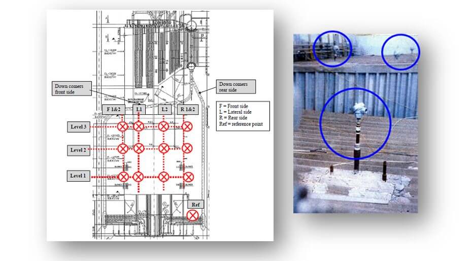
Figure 4. Left: Thermocouple arrangement in critical areas of the boiler furnace,
Right: External view of the industrial water-tube boiler with thermocouples.
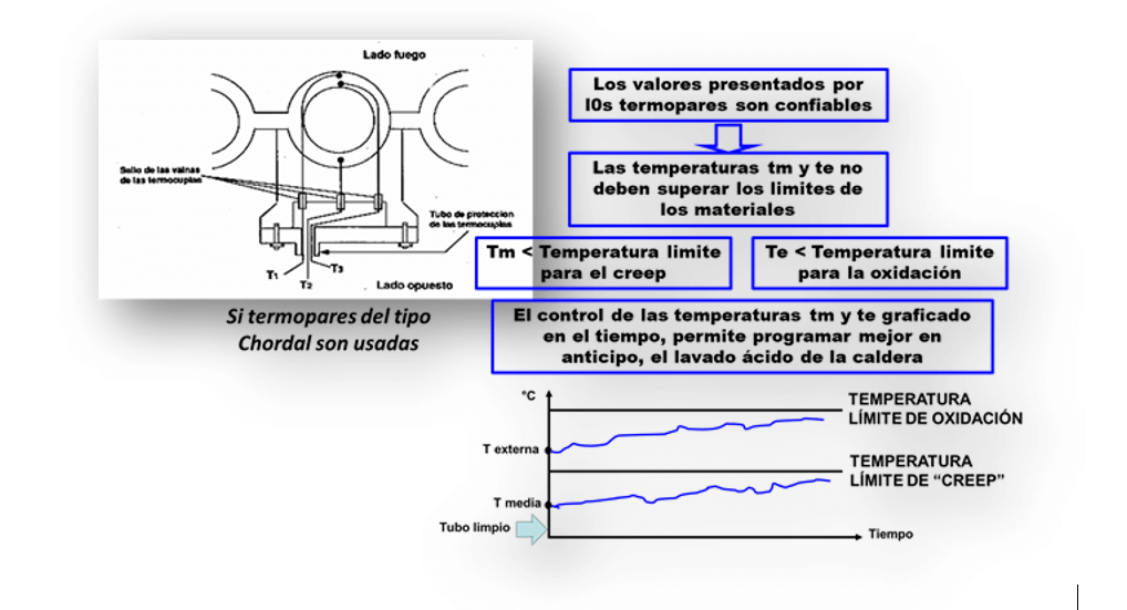
If the thermocouples to be installed on the furnace walls are of the Chordal type, it will be possible to monitor the evolution of the oxidation and creep limit temperatures of the tube material and make decisions such as the right time to plan a chemical cleaning (“See Figure 5”).
Overheater manifolds
Although they are located in chambers isolated from the passage of combustion gases, the ingress of gases and exceeding the maximum temperatures of the materials of these collectors can accelerate the aging of the tubes due to creep.
Secondary superheater steam outlet manifold
Temperature differences between the right and left side of the superheated steam outlet manifold – product steam, can generate problems of expansion differences and thermal fatigue in the joints between the manifold and the pipes.
Superheater tubes
- Whose materials can range from carbon steels (maximum temperature 1,000°F (538°C)), through steels with low alloys (maximum temperatures between 1,000°F (538°C) and 1,200°F (649°C)) that in If these temperatures are equal to or exceeded, it can accelerate the aging of the tubes due to creep.
In the case of stainless steels (maximum temperatures in the order of 1,500°F (816°C)), if the operating temperatures exceed these maximum temperatures, the aging process can be accelerated by Sensitization.
Additional measurement options for increased reliability
The technology is now available for advanced control of combustion performance directly in each burner. The boiler’s control system, based on the monitoring of the flue gas composition, can take corrective operational actions on each burner individually in real time, overcoming the approximate and delayed control of the signal that would be obtained if the flue gas measurement is done as traditionally based on a gas measurement in an area of the duct at the boiler outlet (“See Figure 6”).
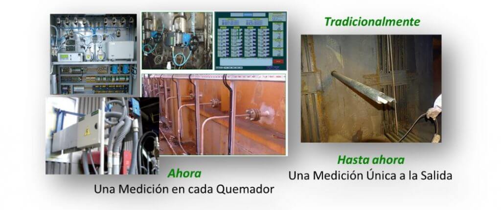
of the boiler.
With this option, the operator has the possibility to increase efficiency, availability and safety. Additionally, combining this with temperature measurements of the metallic elements of the different boiler components will also prevent areas of high heat flux and the acceleration of many of the damage mechanisms that should be expected over the years of operation.
Discussion and Conclusions
According to the opinion of specialists in the area of reliability, there is a possibility that the application of proactive maintenance or reliability-focused maintenance to boilers is limited because the owners or users of this equipment limit their maintenance and inspection actions to the requirements of the regulations where the boiler is installed.
In this work, the convenience of carrying out boiler inspection plans is proposed, based on operating history, which in addition to the history of chemical control and contamination, preservation processes, history of failures, maintenance, repairs, operating regimes (cycling), among other information, are closely related to the temperature values of fluids (combustion gases, water and steam) and metals of critical components of the boiler in different operating conditions (start-ups, shutdowns, cycling conditions and normal conditions). This will allow defining the possible damage mechanisms to be generated in each boiler component.
Inspection plans cannot be limited to visual inspections and thickness measurements, as there are a variety of damage mechanisms that will not be detected and quantified using these methods alone.
Each component is susceptible to specific damage mechanisms
Including metal temperature measurements of boiler tubes and critical boiler elements in routine operational measurements, monitoring and adjustments, and achieving more effectively controlled combustion in real time on each burner, will not only allow immediate corrections to be made to optimize boiler efficiency and availability, but also increase boiler reliability and integrity.
References
1) Royal Decree 2060/2008, December 12, 2008, Supplementary Technical Instruction (ITC EP1 and 2) Annexes “Inspections and Tests” Supplementary Tests, BOE No. 41, Spain 2009. [Real Decreto]
2) R. Tilley, “Boiler Condition Assessment Guideline“, EPRI (Electric Power Research Institute), Fifth Edition, USA 2011. [Reporte Final]
3) The Babcock & Wilcox Company “Steam its generation and use“, Chapter 46, Issue 42, USA 2015. [Libro]
4) C. Lasarte, “Optimization of the Boiler Inspection Plan for More Accurate Maintenance Scopes and Higher Reliability“, ID AEND-3926, 14th National Congress on Non Destructive Testing, Vitoria – Spain June 2019. [Artículo]
5) C. Lasarte, “Recommended Practice for Corrosion Management on Power Boilers of Medium and High Pressure“. ID 191720, EUROCORR 2019, Seville, Spain September 2019 [Artículo]
For more articles visit https://inspenet.com/en/articles/