Summary
Brief introduction of technical aspects and basic notions of the Ultrasonic Guided Wave (UGW) technique.
Introduction
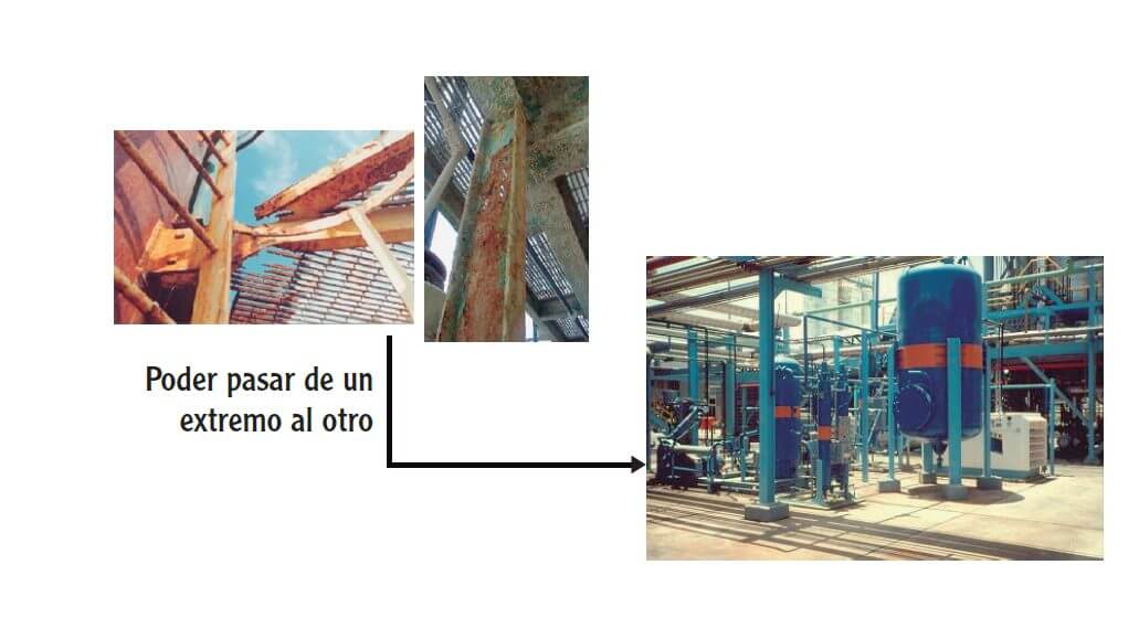
Guided wave technology is a non-destructive method that is used to locate thickness losses (corrosion) in pipes, this can be represented by external or internal corrosion, together with other NDT techniques, the guided wave system will allow maximizing the efficiency of management programs and corrosion control, without affecting the quality of the data.
Guided wave inspections are recognized in the industry as an effective pipeline inspection technology, capable of analyzing large damaged areas. Thanks to the small dimensions of the sensors and the bands, it is now possible to access areas that were previously hidden by the insulation or covering material or that could not be inspected due to their difficult access, which reduces the displacement efforts that they have to make customers.
Recent technological improvements have made it possible to extend the use of guided wave inspections to a wide variety of environments and temperatures. In addition, the results obtained can be analyzed on site, which allows technicians to focus their efforts on the areas of interest and reduce the total costs of evaluating the system.
Pipe inspection
Guided waves consist of the excitation of low-frequency ultrasonic waves that propagate in the axial direction of the pipe, from both sides of the probe collar used for inspection (Figure 1). Several factors influence the maximum sensing distance: the pipe configuration and environment, the type of fluid within the structure, as well as the type of lining.

Torsional waves detect not only general variations in the full cross-sectional area of the pipe, but also changes that have occurred in the material. While the flexural waves are responsible for establishing the exact position of the defects.
Pipe inspection using Longitudinal Guided Ultrasonic Waves, since its inception has come to represent an excellent alternative for operators of fluid transport systems. This technique, made available in the late 1990s, was primarily used for the purpose of detecting corrosion under insulation (CUI).
Although it has in common with the Acoustic Emission that its use is limited to the detection of areas of high potential for failure in a more or less general way, it is a technique that must then be complemented with some other (such as angular UT or PAUT); Which will allow obtaining a higher level of detail of the area where it has been identified with a high probability of presenting a failure in the near future. But we also do this with tank floor inspections, for example. And with the Visual Inspection when we look at atmospheric corrosion and we use a pitting gauge.
In these times the need for efficiency is a constant, and the non-destructive inspection business does not escape this trend. With UGW, or Ultrasonic Guided Wave – We can inspect inaccessible sites, or sections of pipe that would need to be excavated and cut off a highway, for example. We will be able to determine if there is corrosion in sections of pipe with insulation. Sites that would only be accessible with scaffolding or with extreme care and work at heights of considerable risk, such as the upper loading or unloading sections of a fractionation tower, can now be monitored from several meters below.
And as an additional advantage, the inspection is volumetric, and is carried out from a single access point, covering a considerable distance, as can be seen in Figure 2. This makes it especially suitable for monitoring and screening vast sections in record time. With basic UT knowledge, the inspector can be trained and in the field in a relatively short time; A high level of training is not necessary, since it is a monitoring technique and not a quantification technique, at least not as much training as the PAUT, for example.

Obviously it has its limitations, and among them are the sensitivity to changes in the cross section (such as when we have 2 pipes of different schedules in the same section) and the pipe’s stiffness. Although it is true that most systems, by means of advanced signal processing methodologies, allow us to know more about the thickness losses indicated by the collected data, validation with a complementary technique will always be necessary, in order to eliminate of the equation the uncertainty variable.
Technical details
The nature of the acoustic wave on which it is based presents an attenuating/dispersive behavior at the operating frequencies of this type of wave, between 20-100 kHz.
However, enough water has already flowed under the bridge and much more is now known about the phenomenon of attenuation in the first longitudinal mode of the wave, and about dispersion compensation techniques. Thanks to the fact that the first longitudinal mode of the guided wave has a greater number of non-axially symmetric modes, compared to other axisymmetric type modes, it is an improvement in the sizing capabilities of any fault or anomaly. This makes this first longitudinal wave mode suitable for our inspection purposes.
An interesting fact is that this wave can only exist where there is a boundary in which it can propagate. These borders are said to be “Waveguides”, and from there their denotation is derived.
Now, let’s continue this interesting dissertation in the next article!
Bibliographic references
1. “Inspection of pipelines using the first longitudinal guided wave mode” PS Lowea, b*, R. Sandersonb, SK Pedrama, b, NV Boulgourisb, and P. Mudgeb
2. Brunel University, Introduction to Guided Wave Testing Reyaz Sabet-Sharghi*
3. NDT Technician, Vol. 10, No. 1, pp: 6–8


