Introduction
Since the 1970s, a high percentage of coated piping systems have been used to transport natural gas, crude oil and refined products. There are installations that were covered with materials, such as: paraffin tapes, waxes, asphalt and pitch, which are not used today, although they were the most appropriate in their time.
Currently the materials used as coatings have been significantly improved, the need for energy transport and investment requires the protection of aging pipes. The exterior of a buried pipeline is subject to corrosion attack, originally specified coatings were applied at the time of installation to protect the exterior surface.
There are two indicators of significant risks in pipe failures: The age of the system and the types of construction materials, the most appropriate method of control to mitigate these failures is coatings; being, the main tool against external corrosion. NACE establishes the following “All coatings have a useful life in service” including the use with Cathodic Protection (CP).
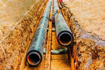
Over time, the coating ages and deteriorates due to soil attack, pipe movement, temperature changes, and flood conditions. Most of the failures occur due to: blows, breaks, detachment, diffusion; As such, it can be seen in Figure 1.
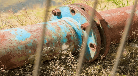
Figure 1. Deterioration of the coating exposed to environmental conditions.
Cathodic Protection (PC)
Coatings alone do not provide complete corrosion protection; therefore, its performance must be reinforced through the use of the Cathodic Protection (CP) method, to extend the useful life of the coatings. During this time, they must maintain their integrity under service conditions in the presence of PC, and act as an electrical insulator for the metal to prevent reactions on the metal surface of the pipe. A damaged coating with exposed areas or aged and with brittle fractures allows the entry of moisture, oxygen and other corrosive species that will require the PC system (higher current) for corrosion control.
In the 1970s, standards (USA) were established so that buried or submerged piping would remain protected with an appropriate coating system added to a PC system designed to protect it.
Coating evaluation
A high dielectric strength coating (voltage/EPS) can provide greater electrical and physical insulation between the pipe and the environment, greater resistance to environmental fluids and the transported product, impact, abrasion, and good adhesion and resistance to peeling. cathodic As the coating ages, it begins to lose properties, such as elasticity and dielectric strength, and can crack and peel.
Generally, ON/OFF measurements are carried out at a closed potential range (CIS or CIPS ) of the line (every 5 years), to verify if the PC system is in accordance with the NACE standard and meets the protection criteria. The technique can also be used to detect point defects in the coating.
cathodic disbondment
The loss of adhesion of the coating on the surface, due to the products of the cathodic reaction. It occurs in the defects through which the PC current will pass into the metal, resulting in a very alkaline environment and the formation of hydroxides on the steel surface (cathodic). This alkaline medium couples with the polarized potential and causes loss of adhesion and detachment. The amount of current flow is determined by the available current and the size of the defects. As defects increase, current flow will increase and more damaged coating will come off the metal, causing rapid detachment and consequent failure (see Figure 2).
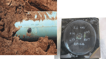
Figure 2. Cathodic Disbondment (Measurement Detail).
Inspection of buried pipes. field evaluation and measurements
The principle of the CIS is to measure the Pipe – Ground potential (P/S) or voltage profile over its length, measuring the potential difference between the buried pipe and the ground, when the PC current is “ON”, or at interruption synchronized with the PC in “OFF”. At test points that do not exceed the depth of the line (approx. 1 m). In places where there is no polarization of the pipe, it indicates that the coating may be deteriorated, which can be seen by the tendency of the potential to fall (less negative) over the time necessary to reach the protection current values (Figure 3 ).
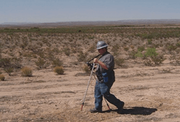
Figure 3. Measurement of the Pipe-Soil potential (P/S).
The areas where coating failures are detected will be verified with other techniques. The trend of falling potential will indicate to the operator that he should perform a voltage measurement with direct current (DCVG) or alternating current (ACVG), as methods of measuring above ground the change of gradient of electrical voltage (vol/long) of the ground. , around the pipe, to locate possible faults. The DCVG and ACVG measurements evaluate in detail the condition of the coating and also identify and classify holidays. These tests are performed in areas where the CIS indicates that more PC is required.
Evaluation of damage found
Evaluation in countryside.
With the PC system operating at its normal output, the DCVG technique applies a Direct Current (DC) signal to the line. Any defect will allow electrical current to flow into the pipe from the adjacent soil causing voltage gradients in the soil above the pipe, which can be measured with a voltmeter Voltage gradients between two reference electrodes placed far apart, are a result of current discharge at sites with defects in the tube coating. The DCVG is able to distinguish between isolated and continuous damage.
Conductance Techniques (TC) (inverse of resistance) are applied to buried pipe sections and determine the general condition of the coating. This technique only applies to dielectric coatings (Figure 4).
CT tests are performed when there are significant changes in the P/S potential and present current requirements in the PC system.
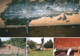
Figure 4. Application of the TC technique in buried pipes.
Areas with high TC values on a given section is a sign of damaged coating. To obtain CT data, the P/S potential is interrupted and current readings are taken at predetermined intervals. Soil resistivity can directly affect CT measurements and must be considered when evaluating a section of pipe coating. Once the coating defect is located on the ground, the visual and electrical inspection of the pipe in service will be able to evaluate the condition and behavior of the external coating system.
These inspections can be done with inverted bell shaped pits for inspection purposes. Many operators perform inspections inside pipes with smart equipment to determine if there is corrosion where it was indicated from the ground.
Protection of buried pipes. Repainted.
The repainting method has been proven to rehabilitate pipelines with damaged coatings (Figure 5). It is considered the best long-term technique to repair coatings and is required when Cathodic Protection is not available. When the coating completely loses its dielectric strength and too much PC current is required to polarize the pipe, a high performance coating system should be properly applied. Repainting will increase the useful life by another 50 years and if combined with a suitable PC it can reach 100 years.
Repainting can be expensive, ranging from $125-550/ft in the US. Repainting of a pipeline may include: excavation, right-of-way (ROW), soil types, environmental limitations, interference currents, permits, and weather conditions. In addition, what is inherent to the application of SR: Abrasive blasting, application and removal of waste.
As the repainted areas increase, the conditions of the PC system must be reassessed, so the current PC could need adjustments or changes, especially to currents and potentials necessary for the repainted pipe.
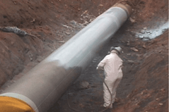
Figure 5. Repainting method for recovery of pipes with damaged coating.
REPAINTING PROCEDURE.
3 steps must be performed (Figure 6).
- The pipe must be uncovered
- surface preparation
- Placement of coatings
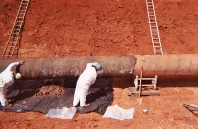
Figure 6. Pipe repainting process
Current coating systems
Currently, the industry of modern coatings has developed widely, especially high-performance Epoxy Systems (long useful life) for cases of buried or submerged pipes. Even for situations that are remote from the field and where the environment is aggressive, there are systems that are tolerant to surface preparation and can even be applied in immersion. There are coatings that are especially resistant to cathodic disbondment.
Buried pipes cathodic protection
If the coating has not reached the point of requiring repainting, a LINEAR (AL) or DISTRIBUTED ANODE system can be installed to increase the PC (Figure 7), as an economical option that provides protection to the pipe and increases its useful life. Typically used for lines in the field, the Impressed Current Design PC (ICCP) installed during construction is a remote anode that provides current protection for miles of pipeline. This distribution depends on the resistance between the bed and the protected pipe. The current density decreases with the distance between the anode bed and the structure.
Linear anode systems
Deep anode systems were installed where ROW conditions did not allow installation of a linear remote bed and/or space was restricted by possible interference or few local facilities. The cathodic protection systems were spaced with an arrangement of anodes distributed with the measurement sites. This method of control together with repainting, has been successful, it is 100% effective (over 255 ROW miles, per axle.). Rehabilitation of this pipeline with repainting was completed in 2 years and additional linear PC anodes continue to be installed as the coating ages.
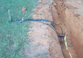
Figure 7. Distributed anode system on PC.
Conclusions.
- The solution with PC should be the first option for the rehabilitation of pipes, if the deterioration of the coating is determined in time.
- The use of PC with repainting is a very economical strategy to achieve long term pipe protection.
- Pipe integrity can be restored by using PC both to compensate for coating deterioration and to protect repainted segments.
- Engineering designs and evaluation analysis must be carried out by qualified personnel to ensure that the chosen rehabilitation strategy is appropriate.

About the author: Daniel Contreras. ing Chemist, M.Sc, NACE Certificate in Coatings. Level 1, 2 and 3, With more than 40 years in university teaching and research and advisor in the area of coatings at an industrial level