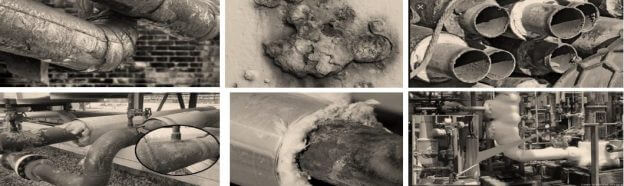
What is Corrosion Under Insulation (CUI)?
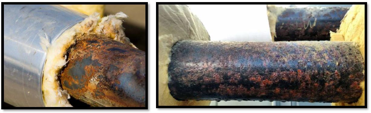
Corrosion Under Insulation (CUI, Corrosion Under Isolation) is a phenomenon that normally affects carbon steel pipes and pressure equipment, as a result of the entry or condensation of water under the thermal insulation. Within this category of corrosion can also be included Corrosion Under Heat Insulation (CUF, Corrosion Under Fireproofing for its acronym in English), generated by the same cause of piping in pressure equipment.
The mechanism of corrosion under the insulation
This type of damage involves three factors:
• Availability of oxygen.
• High temperature.
• Concentration of dissolved species.
Normally, as the temperature increases, the amount of dissolved oxygen in the solution decreases as the boiling point is reached; which reduces corrosion. However, on the surface covered by the insulation, a patch effect is created that retains moisture; causing the formation of a closed system. Measured corrosion rates associated with under-insulation corrosion continue to trend higher corrosion rates commonly associated only with pressurized systems. The cases in which the precipitates of the atmospheric constituents are trapped on the metal surface by the insulation, such as: chlorides and sulfuric acid, they can concentrate, accelerating the corrosion mechanism. In some cases, chlorides are present in the insulation, greatly promoting corrosion of the underlying moisture-laden surface.
How is it detected?
There are several techniques available for locating this corrosion phenomenon. This article exposes the three techniques most used by a large number of Non-Destructive Testing service companies. The following are described below:
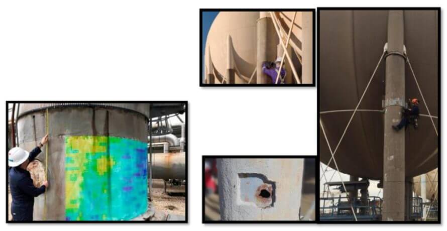
The Pulsed Eddy Current (PEC)
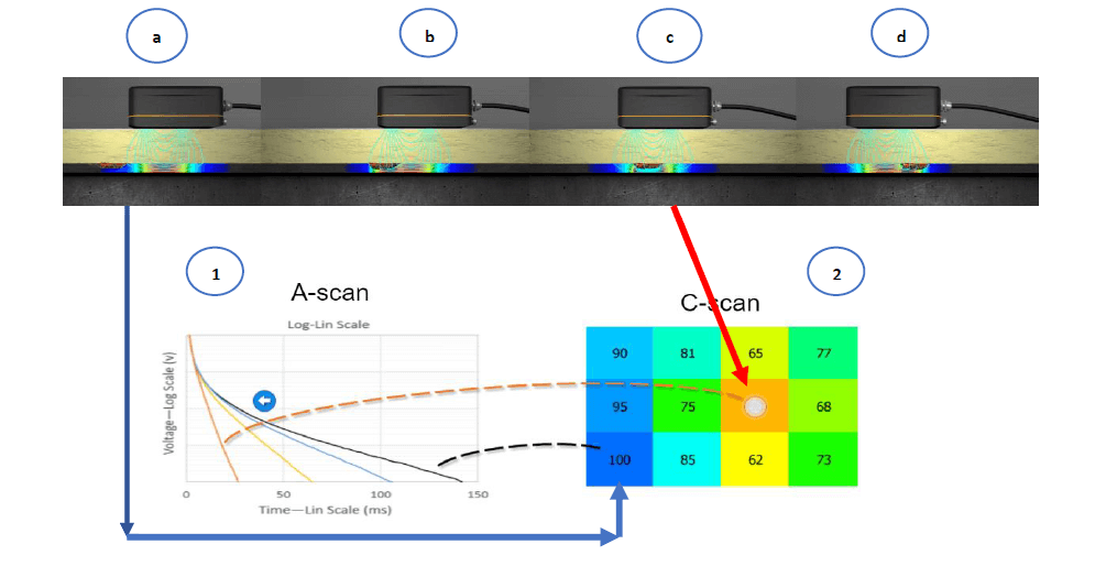
Pulsed Eddy Current (PEC) is an electromagnetic inspection technique used to detect wall loss in ferromagnetic structures such as carbon steel and cast iron. Provides a relative volumetric measurement converted to an average thickness measurement based on the calibration area.
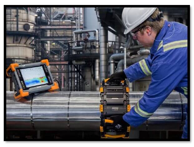
Principle of the technique. To generate and capture PEC, a magnetic field is first created by an electrical current in the probe coils (a). Penetrates through sheathing, any non-conductive insulation (concrete, silicate, waterproof jacketed insulation, or marine vegetation) (b) and stabilizes in the thickness of the component. Then the broadcast is cut off. This abrupt change induces eddy currents that will be captured by the probe. The EddyFi Lyft instrument measures the rate of decay (1) and an advanced signal processing algorithm translates the electromagnetic signal into an average thickness reading (2) over the sonde footprint.
Technological applications:
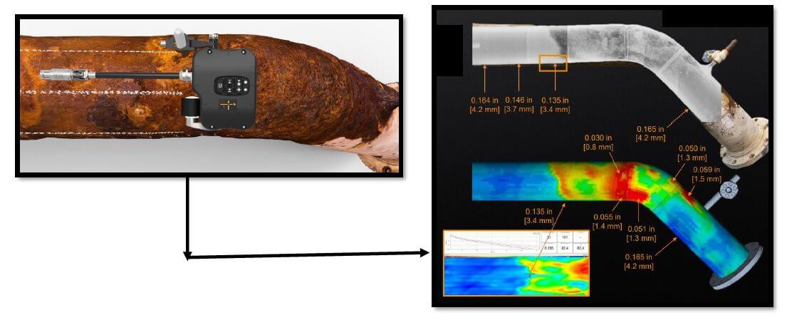
For corrosion under insulation (CUI), the most recent development is the PECA probe, PECA stands for Pulsed Eddy Current Array.
High productivity PECA probe for CUI inspections
- Inspection method in API RP 583 – 2014
- 18 in (457 mm) single pass coverage
- From 6 in. (152 mm) to flat surface
- Inspect up to:
- 1 inch (25 mm) material thickness.
- 4 in. (102 mm) insulation/peelback.
- 1 mm (0.04 in) aluminum waterproof jacket.
- 0.06 in. (1.5 mm) stainless steel waterproof jacket.
CorrosionLow Fireproofing
High productivity PECA probe for CUF inspections
✓ Inspection method in API RP 583 – 2014
✓ 457 mm (18 in.) single pass coverage
✓ Integrated locking mechanism to adjust pipe outside diameter from 152mm (6in) total including insulation to flat surface
✓ Inspect up to:
- 1 in. (25mm) material thickness
- 4in (102mm) Flame Retardant
- Reinforced concrete
- Concrete
- silicate with coating
Scabs and blisters
✓ Safe evaluation of the remaining WT on the scab
✓ Dual 3 sensor array covering 3 inches
✓ Spatial triangulation to detect and measure smaller flaws
✓ Smaller footprint on a PEC sensor.
- FP0: 0.87 inches (22)
If you want to know more about these and other techniques, get in touch with us!
References:
Own source