Table of Contents
- What is vibration analysis?
- What is vibration analysis for?
- Physical principles: amplitude, frequency and overall value
- Technical definition of mechanical vibration
- Vibration analysis failure methods
- Permissible cryerial limits
- Good practices in condition monitoring
- Importance of analysis in predictive maintenance
- Frequency and amplitude of failure indicators
- Overall vibration measurement (Overall value)
- Failure diagnosis case studies
- Sensors and tools in vibration analysis.
- Conclusions
- References
By means of vibration analysis, predictive maintenance technicians of rotating equipment are able to monitor, analyze the failures and condition of machinery components and obtain the most accurate diagnosis possible.
In this article, a brief explanation of typical analysis methods such as: time domain, frequency domain, modal analysis, time wave, phase measurement, among others; as well as the most important concepts and tools necessary to perform the analysis of machinery.
What is vibration analysis?
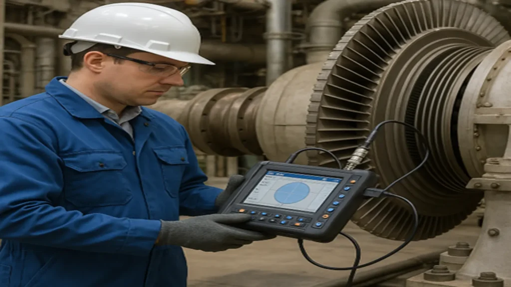
In the dynamic environment of modern industry, where operational efficiency and service continuity are strategic priorities, vibration analysis and diagnosis has become one of the most powerful tools of predictive maintenance.
This technique makes it possible to detect, interpret and anticipate a wide range of mechanical failures in rotating equipment (such as pumps, compressors, turbines and electric motors) by capturing and evaluating the vibrational signals they generate during operation.
The vibrational behavior of a piece of equipment is, in essence, a reflection of its internal condition. Through accelerometers, speed or proximity sensors, key variables such as amplitude, frequency and phase can be measured, whose evolution reveals the presence of unbalance, misalignment, mechanical looseness, cavitation, resonance or lubrication problems, among others.
Thanks to algorithms such as Fast Fourier Transform (FFT) and other spectral analysis tools, these signals are transformed into understandable and actionable information for technical personnel.
What is vibration analysis for?
Vibration analysis allows the early detection of a wide range of mechanical failures. Among the most common defects that can be identified are:
- Misalignment of shafts and couplings
- Rotor dynamic unbalance
- Mechanical and structural backlash
- Bearing failures (pitting, wear, cracks)
- Lubrication problems
- Cavitation in pumps
- Structural resonance
Beyond simple monitoring, vibration diagnostics enables proactive maintenance management, improving asset reliability, reducing unscheduled downtime and extending the life of critical components.
In an increasingly digitized world, this discipline is also being integrated with online monitoring systems, intelligent sensors (IoT) and artificial intelligence algorithms to achieve continuous, accurate and real-time monitoring. This tool is fundamental in predictive maintenance, as it avoids unscheduled downtime, reduces repair costs and increases the useful life of assets.
Vibration analysis is a discipline that makes it possible to identify and anticipate mechanical failures before they become costly shutdowns. Each measurement recorded by sensors (such as accelerometers) feeds a spectral interpretation process that, when properly applied, transforms raw data into reliable knowledge.
This process of vibration analysis requires a critical, meticulous and investigative attitude on the part of the specialist. It is not enough to detect an anomalous frequency; it is necessary to understand its origin, correlate it with the dynamic behavior of the equipment and translate it into an accurate technical recommendation.
Physical principles: amplitude, frequency and overall value
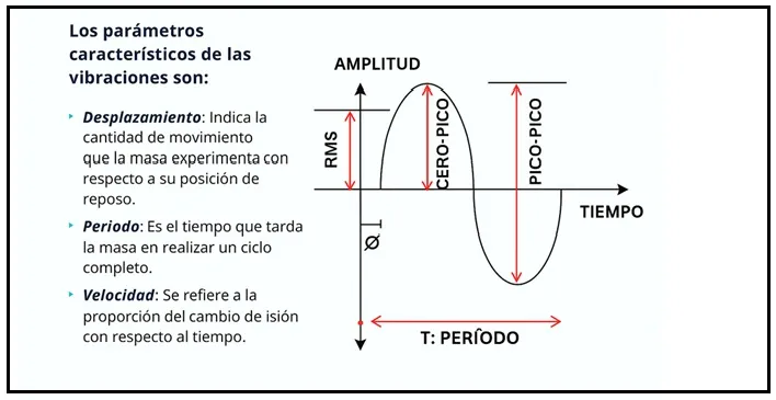
Amplitude and frequency are the two main parameters in vibration. Frequency indicates how many times a vibration occurs in a given time, and is associated with the type of failure. Amplitude indicates the energy of the vibration and represents the severity of the fault.
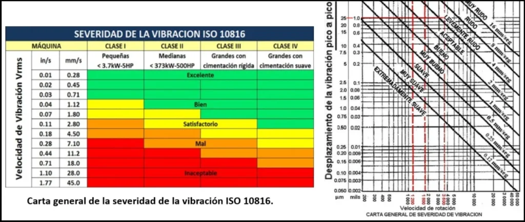
The Overall value is a global indicator of the vibrational level, usually measured in mm/s RMS. This value is compared against severity criteria (such as ISO 10816 or API 610) to evaluate the overall condition of the equipment.
Technical definition of mechanical vibration
Vibration is defined as the oscillatory motion of a mechanical component subjected to internal or external excitation. This response can be measured as a function of time or frequency, allowing the identification of patterns that alert the incipient deterioration of critical elements, such as bearings, shafts or couplings.
Vibration analysis failure methods
There are several analysis methodologies, among them:
- Time domain: evaluation of the raw waveform.
- Frequency domain: spectral analysis by FFT (Fast Fourier Transform).
- Modal analysis: determination of natural modes and structural resonances.
- Phase measurement: used to confirm misalignment and assembly problems.
- Envelope detection: very effective in early detection of bearing failures.
The time and frequency diagrams of the received signals, transverse incident waves and the longitudinal wave generated individually, are shown in the following image.
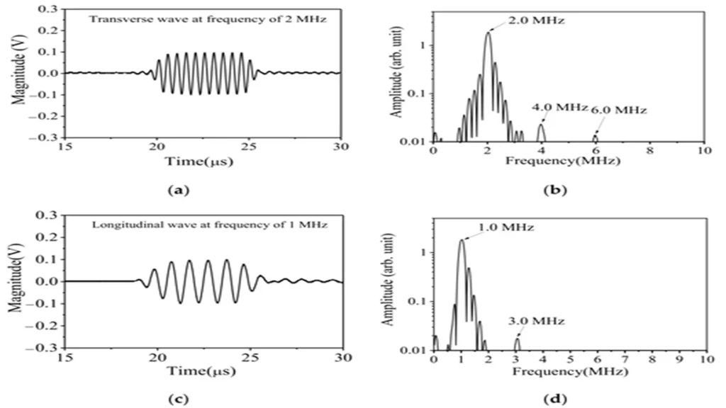
Table 1. Relationship between typical faults and their spectral signature.
| Common Fault | Expected Frequency | Spectral Symptom | Typical Severity |
|---|---|---|---|
| Unbalance | 1X RPM | Dominant peak at 1X | Low |
| Misalignment | 2X–3X RPM | Multiple harmonics | Medium |
| Mechanical Looseness | Low frequency | Low-frequency peak + harmonics | High |
| Bearing Failure | High frequency (10–20 kHz) | Sidebands (Envelope) | High |
Permissible cryerial limits
Vibration: severity criteria
Acceptable vibration values are defined by standards such as ISO 10816-3 and ISO 20816-1, and API 610 for centrifugal pumps. The following is a basic guide:
Table 2. Severity Levels According to ISO 10816 (in mm/s RMS)
| Machine Type | Good | Acceptable | Unacceptable |
|---|---|---|---|
| Small pumps (<15 kW) | <1.8 | 1.8–2.8 | >2.8 |
| Medium pumps (15–75 kW) | <2.8 | 2.8–4.5 | >4.5 |
| Large pumps (>75 kW) | <3.5 | 3.5–5.6 | >5.6 |
It is important to consider that some equipment has unique vibration analysis patterns, so baseline values must be established.
Dynamic balancing is the process by which the vibration caused by an excess of mass in an area of the rotor that causes its center of mass to move away from its geometric center is reduced.
There are 3 ways to evaluate good balancing:
- ISO-1940 standard (quality grade on floating bases).
- ISO-10816 Standard (by Machinery Classes)
- Residual Unbalance (in g.mm/kg)
Good practices in condition monitoring
- Know the normal vibrational behavior of each machine.
- Observe trends to detect deviations.
- Install sensors on rigid surfaces and at critical points (horizontal, vertical, axial).
- Use thermal and safety protections when measuring near hot pipes or seals.
- Avoid interference in the cable routing.
Importance of analysis in predictive maintenance
In predictive maintenance programs, continuous monitoring through vibration analysis allows detecting failures before they materialize in unscheduled shutdowns.
It is not enough to replace defective components; it is essential to identify the root cause to avoid recurrence. Vibrational analysis provides objective data for effective corrective actions.
Frequency is the number of times an event occurs in a given period (a period denoted by T); it is the time required for a complete vibration cycle to pass through a given point. The event being a vibration cycle.
Frequency and amplitude of failure indicators
The correct identification of the frequencies present in the vibrational spectrum allows them to be associated to specific failure mechanisms. The amplitude, on the other hand, provides a quantitative estimate of the severity of the problem. Both factors must be interpreted together for an accurate diagnosis.
The frequency at which the vibration occurs indicates the type of failure. That is, certain types of failures exhibit typical behavior occurring at certain and specific frequencies. When we are able to establish the frequency at which the vibration occurs, we get a more defined picture of what might be causing it.
The amplitude is the size of the vibration signal. This amplitude determines the severity of the fault. The larger the amplitude, the greater the vibration and obviously the greater the problem.
Overall vibration measurement (Overall value)
The Overall value is an overall indicator of the vibrational level within a range of frequencies. Comparing this reading with established severity criteria allows the overall condition of the equipment to be evaluated. Increases in this value suggest the appearance or evolution of mechanical failures.
It is the total vibration energy measured within a frequency range. When we proceed to measure the overall machine vibration of a machine and compare that reading with its normal value as determined in the vibration severity criteria tables for machines, it will indicate the current condition of the machine. A higher than normal overall reading obviously indicates that something is causing a machine component to vibrate more.
Vibration is considered as the best operating parameter to measure low frequency dynamic conditions, such as unbalance, mechanical backlash, misalignment, structural resonance, soft base, shaft deflection, bearing wear. Permissible vibration limits for centrifugal pumps can be found in API 610 or ISO 10816-7.
Failure diagnosis case studies
A worn bearing can generate a high frequency peak detectable by FFT analysis. But if a previous misalignment is not corrected, the new bearing will also fail.
Case of a Flexicoker plant feed pump P-2101 B
Example: in a centrifugal pump, an overall value exceeding 4.5 mm/s in axial direction may indicate a misaligned rigid coupling. Correct interpretation of this data allows effective maintenance decisions to be made.
This was the case of a P-2101 B pump feeding a Flexicoker plant, which presented abnormal vibration levels and after evaluation and analysis it was determined that a misalignment was causing this equipment behavior. The recommendation was to align using a laser type equipment and this abnormality was corrected. The pump returned to its normal operating levels.
Blower vibration diagnostic case study
High vibration in a boiler blower due to unbalance is a common problem and can be solved by several corrective actions. Below is a step-by-step approach that was used on a boiler blower at an Oil Refinery Industrial Services facility to effectively diagnose and fix the problem.
Step to balance a blower and why is it important?
During blower rotor balancing, technicians use a balancing machine to measure the blower’s vibration amplitude and determine where its frequency increases. They then clean the blower and make the necessary adjustments to balance it, improving its efficiency.
1. Inspect for foreign material and dirt: As a first step, check for debris: Inspect the blower rotor for debris, dust or buildup (such as insulation, paper or other foreign material) that can cause imbalance. Even a small amount of accumulated debris can cause significant vibration.
2. Clean thoroughly: Remove any material adhering to the blower rotor and make sure all surfaces are clean and free of dust or debris.
3. Check for physical damage: Visual inspection: Look for bent, cracked, or worn blades, or any physical deformation of the rotor or hub.
4. Repair or replace: If any damage is found, repair or replace the blower rotor as necessary to restore proper balance.
5. Inspect Assembly: Tighten: Make sure all anchor bolts are tight. A rotor with loose anchor bolts can simulate or worsen unbalance symptoms.
6. Bracket condition: Check the integrity of mounting surfaces and structures. Damaged or inadequate mounts can contribute to vibration.

7. Perform rotor balancing: The best balancing method for a rotor depends on its length and operating speed. For short rotors and low speeds, static balancing may be the most—ade-quate. For long rotors and high speeds, dynamic balancing is required, which can be in one or two planes.
There are balancing machines, which can be static or dynamic, and vibration analyzers with sensors and specialized software are the equipment needed to perform a satisfactory balancing. Reinstall and test: Once the balancing job is completed, reinstall the blower rotor and secure it firmly. Run the blower at full speed to confirm that vibration has been reduced.
Sensors and tools in vibration analysis.
1. Accelerometers: Accelerometers are piezoelectric or MEMS sensors designed to measure the vibrational acceleration (m/s² or g) of a surface. They work by means of a piezoelectric crystal that generates an electrical charge proportional to the acceleration when subjected to dynamic forces.
- Typical applications: Detection of unbalance, misalignment, bearing failures and mechanical clearances.
- Medium and high frequency capture (>10 Hz to 10-15 kHz).
- Best practices:
- Rigid fixing by screw or magnetic base.
- Shielded cabling.
- Mounting on rigid surfaces.
2. Proximity Sensors: These non-contact sensors detect the variation in the distance between the sensor and a conductive surface, typically the axis of the equipment, using the eddy current principle.
- Typical applications:
- Turbine, compressor and critical machinery monitoring.
- Direct measurement of shaft displacement.
- -Orbit analysis and rotor dynamic phenomena.
- Good practices:
- Calibration according to API 670.
- Accurate sensor alignment.
- Periodic gap and signal verification.
3. RMS velocity (Root Mean Square): The RMS velocity represents the total vibrational energy of a signal, expressed in mm/s or in/s. It is ideal for evaluating overall vibration severity.
- Typical applications:
- Evaluation of overall machine condition.
- Comparison with ISO 10816/20816 standards.
- Use in continuous monitoring.
- Best practices:
- Measurement in three directions.
- Establishment of alarm thresholds.
- Adequate filtering of the frequency range (10 Hz to 1 kHz).
Conclusions
Vibration analysis is much more than a diagnostic technique: it is a strategic tool that allows the engineer and the predictive specialist to decipher the hidden language of machines.
Through the precise measurement of mechanical oscillations (captured by accelerometers and analyzed with frequency spectra) it is possible not only to detect incipient faults, but also to understand their nature, their evolution and their possible operational impact. This analytical capability, when applied with rigor and technical intelligence, transforms the practice of predictive maintenance into a science of anticipation and reliability.
Adopting an investigative, inquisitive and meticulous posture in the interpretation of spectral signatures allows the specialist to not only detect a symptom, but to go deeper into the root cause, propose adjusted corrective actions and raise the level of operational reliability.
In this context, the analysis of a machine’s behavior through its vibration signature ceases to be a routine and becomes an art of technical precision, where each frequency revealed is a clue and each pattern an opportunity to improve performance, prevent costly shutdowns and protect critical assets.
In addition, vibration analysis integrates efficiently with other condition monitoring techniques such as oil analysis, infrared thermography and ultrasound. This integration allows building reliability-based maintenance (RCM) systems, improving the ability to forecast and plan shutdowns.
References
- Web Site: www.skfreliability.com
- Moubray JM, Development in Reliability – centred Maintenance.
- Bowers, SV; Integrated Strategy for Predictive Maintenance of AC induction motors.
- David Trocel GTS Confiabilidad C.A. www.confiabilidad.com.ve
- https://www.cambridge.org/core/books/abs/dynamics-of-rotating-machines/introduction-to-vibration-analysis
- https://www.researchgate.net/publication/354476610_Detection_and_Location_of_Surface_Damage_Using_Third-Order_Combined_Harmonic_Waves_Generated_by_Non-Collinear_Ultrasonic_Waves_Mixing