Table of Contents
- What API 650 covers and where it ends
- Plate types in API 650 tanks
- Key aspects you must understand from API 650
- API 650 compliance during construction
- Component based design: The tank as a system
- Accessories required for operation
- Joints and welds: Integrity during fabrication and erection
- Inspection, testing, and NDT
- Capacities and levels: From design to setpoint
- Corrosion: Coatings, linings, and cathodic protection
- Vapors: Sealing, venting, and recovery
- Innovations compatible with API 650
- Conclusions
- References
- FAQs: Frequently Asked Questions
API 650 is the most widely used standard for the design, fabrication, erection, and inspection of aboveground vertical steel storage tanks. Its value lies not only in “complying with a standard,” but in turning a critical piece of equipment into a predictable and defensible asset: it defines minimum plate data, design conditions, construction criteria, dimensional control, and verification through inspection and testing.
This article shows how the API 650 standard connects key components—foundation, bottom, shell, roof, and accessories—with operational performance: levels and capacities, weld integrity, corrosion control, venting, and vapor management. The objective is to establish a common language between engineering, QA/QC, and operations, based on verifiable requirements.
What API 650 covers and where it ends
API 650 defines the minimum verifiable framework for the design, fabrication, erection, and inspection of flat-bottom, cylindrical steel tanks with open or closed roofs intended for storage service at pressures near atmospheric conditions. Its primary contribution is establishing a uniform technical framework for engineering and construction: design criteria, construction requirements, dimensional control, and inspection evidence that demonstrate tank conformity and ensure consistency among contractors, sites, and projects.
In practice, API 650 does not design an “ideal cylinder”; it designs a real piece of equipment that must withstand environmental and operational loads. For this reason, the standard drives decisions that directly impact reliability and safety: roof configuration selection, bottom and annular details, reinforcements and openings, and quality controls that prevent distortions, leaks, and rework. From an engineering perspective, it reduces variability in expected performance; when applied correctly, the tank performs according to its design conditions.
It is important to understand that API 650 is not a rigid document. It includes annexes and supplementary requirements through which design can be adapted to different scenarios: special roofs (including covers or domes when specified), structured equipment documentation (data sheet), considerations for under-bottom systems when required by the project, and additional criteria that help maintain engineering traceability.
Where does it end? API 650 does not replace three disciplines that always appear in field practice:
(1) tank gauging and traceable capacity tables (API MPMS / ISO),
(2) corrosion control and coatings / cathodic protection (API 651 / API 652), and
(3) overfill protection philosophy, venting, and emissions management (API 2350 and API 2000).
Plate types in API 650 tanks
To understand API 650 from a construction perspective, it is useful to organize the tank by plate families, since each involves different design, welding, inspection, and corrosion criteria:
- Shell plates: govern hydrostatic load integrity and structural stability.
- Bottom plates (bottom / floor plates): dominate leak tightness, drainage, residual product, and corrosion behavior.
- Annular plate: the perimeter zone subjected to the highest demand under the first shell course; it is usually specified with more demanding structural criteria.
- Roof plates: conditioned by environmental loads, accessories, ventilation, and, when applicable, special configurations (IFR/EFR or covers)
Key aspects you must understand from API 650
In practical terms, the aspects that provide the most value to professionals—and those most frequently addressed in projects—can be summarized in the following areas:
- Scope and organization of the code, and definition of design conditions.
- Material selection including corrosion allowance and mechanical properties.
- Shell calculation (thickness by design height and hydrostatic load).
- Structural stability: wind girders / stiffening rings and verification against external actions.
- Bottom, annular plate, and roof design (fixed, floating, and internal configurations).
- Connections (nozzles, reinforcements, windows, flanges / necks) and their effects on integrity and operation.
- Fabrication and QA/QC: welding, NDT, and pre-commissioning testing.
- External loads: wind load combinations and overturning moments; when applicable, seismic effects and anchoring.
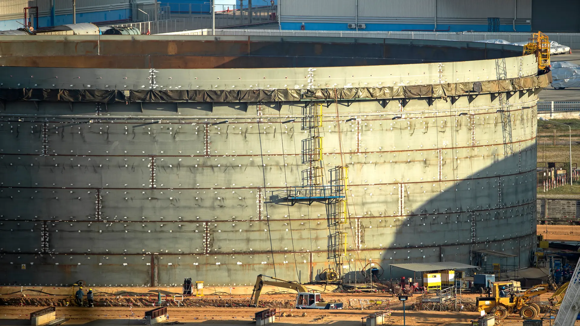
API 650 compliance during construction
- Materials and thickness: verify specification limits according to Section 4; incorporate corrosion allowance according to service.
- Design rules: apply Section 5 and relevant annexes for shell, bottom / annular, and roof.
- Welding and NDT: WPS/PQR and qualified welders; NDT according to Section 8 and leak testing where applicable.
- Traceability: material certificates (MTR / Mill Test Reports), welding records, NDT, and test documentation; nameplate and documentation including the applicable edition.
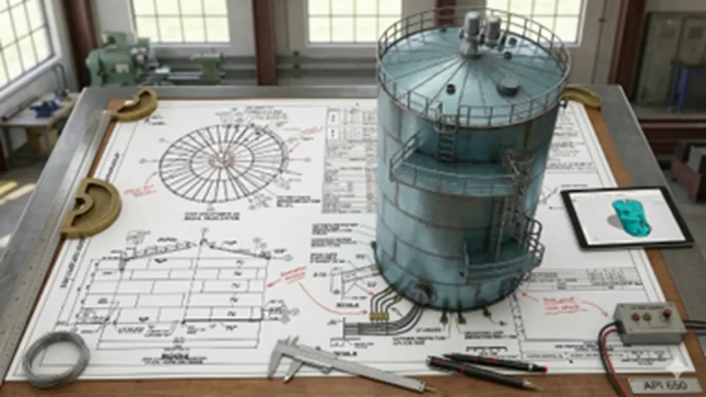
Component based design: The tank as a system
Reading API 650 by components allows design and construction requirements to be translated into verifiable operational criteria. The importance of tank design lies in defining engineering behavior throughout the asset’s service life: structural integrity, leak tightness, deformation control, operational capacity, and environmental performance.
Under these premises, each element (foundation, bottom, shell, roof, and accessories) imposes geometric, structural, and environmental limits that, during operation, become critical levels, useful capacities, and integrity barriers.
Foundation and ring
The foundation conditions settlement, out-of-roundness, and plumbness. When differential settlement occurs, secondary stresses increase in the shell, in the shell-to-bottom corner weld, and in nozzles. Additionally, the volume–level relationship loses stability and the capacity table may no longer represent the “as-built” condition.
Primary and secondary containment
Primary containment: the tank itself (bottom + shell + welded joints + nozzles), designed and verified to retain the stored product.
Secondary containment: the external system intended to prevent a primary containment loss from becoming a discharge to soil or water.
Under bottom leak detection and subgrade protection
API 650 includes a normative annex for Undertank Leak Detection and Subgrade Protection (Annex I), aimed at under-bottom solutions and subgrade protection (prepared soil layer) when required by the project. This is especially relevant when environmental consequences or soil-side corrosion risks justify an early detection strategy.
Bottom and drainage
The bottom defines the actual lower boundary: slopes, sumps (floor or center sump), elevation of low nozzles, and sediment accumulation determine minimum heel and non-pumpable volume. If bottom corrosion degradation occurs (product side or soil side), operations tend to restrict the usable range and the net working capacity becomes governed by integrity criteria rather than geometry.
From a corrosion control perspective, it is useful to separate mechanisms and barriers:
- Soil side: the classic reference is bottom cathodic protection according to API RP 651.
- Product side (internal): API RP 652 guides the selection and application of bottom linings as a method of internal corrosion control.
- VCI / ICV (volatile corrosion inhibitors): API TR 655 provides guidance for the use of Vapor Corrosion Inhibitors as an alternative or complementary measure to mitigate soil-side corrosion, highlighting a key technical limitation: the foundation must allow containment of the VCI beneath the bottom for the method to be effective.
In design and operation, this translates into a practical criterion: drainage systems, sumps, and free-water management must be defined consistently with the selected corrosion control method (CP, lining, VCI, or combinations) and with site environmental requirements.
Shell and openings
The shell is configured in courses (rings); as liquid level increases, the highest demand occurs in the first course and its welds. Openings such as cleanout doors, manholes, and nozzles generate stress concentrations; therefore dimensional control and NDT around openings become integrity elements rather than administrative requirements.
Operationally, nozzle location and reinforcement affect filling and emptying rates, flow-induced vibration, and leakage risk due to fatigue or distortion. When shell ovality or tilt occurs, level-to-volume conversion requires a traceable “as-built” capacity table to avoid inventory and operational limit errors.
Roofs: Fixed and floating
The roof transforms the “geometric maximum” into a “maximum allowable” limited by integrity and emission restrictions. In API 650, common configurations include:
- Fixed conical roof and dome roof, selected based on service, environmental loads, and accessory configuration.
- External floating roof (EFR) and internal floating roof (IFR), preferred when evaporative losses must be minimized by reducing vapor space.
In floating roofs, performance depends critically on the seal system and deck drainage. Seal integrity loss increases emissions and can compromise operability (water accumulation, flotation problems, and unexpected stresses).
As a complementary solution, aluminum geodesic domes designed under API 650 Annex G are used to protect the roof system from weather and stabilize operating conditions.
Accessories required for operation
Accessories often define the operational limits in practice:
- Vents and P/V valves: determine filling and emptying rates and protect against vacuum or overpressure; their sizing is typically managed using API 2000 as a complementary reference.
- Level measurement and instrumentation: radar / servo / hydrostatic measurement, alarms, and setpoints must align with tank limits and the overfill protection philosophy (API 2350 as complementary reference).
- Platforms, stairs, drains, and process connections: influence inspection accessibility, maintenance safety, and operational reliability.
Joints and welds: Integrity during fabrication and erection
In an API 650 tank, mechanical integrity is conditioned by the welding system: procedure qualification (WPS / PQR), welder and operator qualification, consumable selection and control, essential variable control, and welding sequence to limit distortions; all must be supported by inspection and NDT.
In general terms, the shell is fabricated mainly with butt joints. In the perimeter zone, the annular plate is also typically executed with butt joints due to its structural function under the first course. In the bottom, lap joints with fillet welds are common; and the bottom-to-shell connection is completed with the shell-to-bottom corner weld, normally a continuous fillet weld where leak tightness and discontinuity control are critical.
Quality is not “declared”; it is built and demonstrated in three technical stages:
- Preparation and fit-up: alignment, bevels, cleaning, joint spacing / fit-up, and dimensional control.
- Execution (welding): variable control, heat input, welding sequence, and technique to limit distortion and residual stresses.
- Verification (QA/QC): visual inspection and applicable NDT (RT / UT / MT / PT depending on joint type and criticality). Leak tightness must also be confirmed in sensitive joints, especially bottom welds and the bottom-to-shell corner weld. Early leak detection reduces rework, decreases the risk of subgrade damage, and preserves the intended operating condition.
If any of these stages fail, the impact is immediate: increased rework, compromised reliability of critical joints (especially bottom-to-shell and penetrations), and possible operational restrictions due to risk management or early repair.
As a trend compatible with API 650, mechanization and automation of shell course and circumferential (girth) welding have increased to improve repeatability, productivity, and process variable control, especially in large-scale projects.
Inspection, testing, and NDT
API 650 requires the tank to be delivered with a verification package prior to commissioning: visual inspection, NDT where applicable, localized leak tests, and, for new or reconstructed tanks, a hydrostatic test as a global demonstration of integrity and tightness.
Mandatory NDT and scope according to API 650
The standard concentrates requirements in Section 8 (Inspection / Examination) and distinguishes between joints requiring RT / UT and joints where the focus is leak tightness through leak detection methods.
- Radiography (RT) is required for specific critical joints: Shell butt-weld joints, Annular plate butt joints, Flush-type connections with butt welds
- For the bottom (lap joints) and other welds where RT is not typical, control focuses on VT plus leak testing, with the vacuum box being the most common method to verify bottom weld tightness.
Hydrostatic test
For new or reconstructed tanks, the hydrostatic test is normally required before commissioning. Even though API 653 includes criteria for exemption in specific cases, it assumes that a new tank is hydrostatically tested according to API 650.
UT “instead of” RT and advanced NDT
As an evolution of the standard, Annex U was incorporated to prescribe the rules under which ultrasonic testing (UT) may be used instead of radiography for evaluating butt welds.
In practice, this opens the door to advanced UT techniques (such as TOFD / AUT) and digital radiography as improvements in traceability and safety, provided they comply with the applicable annex and project specifications.
Capacities and levels: From design to setpoint
To manage capacities accurately, operational levels must align with design limits and protection functions. Therefore, levels are organized as barriers:.
- Design barrier: level up to which the tank was designed to contain liquid with the design specific gravity (integrity limit).
- Operational barrier: normal operating level that stabilizes logistics and reduces exposure to deviations.
- Safety barrier: level that triggers actions to prevent overfill (alarm, intervention, and/or shutdown)
API 2350 complements this approach by establishing minimum requirements for overfill prevention and assigning functions to each protection level.
Net working capacity is defined between a maximum operable level (limited by roof, venting, and protection systems) and a minimum operable level (suction limitations, residual volume, and water/solids management). When custody transfer or high accuracy is required, the capacity table must be traceable; ISO 7507 includes 3D scanning methods for calibration and capacity table compilation, including tilt correction within acceptable limits.
Corrosion: Coatings, linings, and cathodic protection
API 650 defines the tank; service life depends on a corrosion control program. A practical technical approach is to separate mechanisms and barriers between product side and soil side.
Bottom cathodic protection
For the soil side, API RP 651 addresses bottom corrosion control through cathodic protection practices applicable to both new and existing tanks.
Internal linings and coatings
For the product side, API RP 652 guides the selection and application of bottom linings: materials, surface preparation, application, curing, and inspection.
A key point: an internal lining reduces corrosion from product or water exposure but does not eliminate soil-side corrosion risk by itself. Therefore, when risk justifies it, it is integrated with CP and/or subgrade barrier systems.
For both external and internal coatings, surface preparation is the critical performance variable. Within the AMPP framework, specifications such as SSPC-SP 5 / NACE No. 1 (White Metal Blast Cleaning) are used to define cleanliness and verify final surface condition prior to coating application.
Vapors: Sealing, venting, and recovery
Vapor control integrates design, mechanical safety, and environmental compliance. In API 650 tanks, system performance depends on three functions: venting, sealing (in floating roofs), and, when applicable, recovery.
Venting and mechanical protection
The tank must maintain pressure balance during filling/emptying cycles and thermal changes. API Std 2000 is commonly used as the reference for normal and emergency vent sizing in atmospheric and low-pressure tanks to avoid vacuum or overpressure conditions that could compromise integrity and operation.
Floating roof seals
In floating roofs, the peripheral seal system is critical for emission control. In addition to the design framework of API 650 (Annex C for EFR), U.S. regulations require verifiable seal conditions (physical integrity, absence of significant discontinuities) and gap control through inspection and acceptance criteria.
Vapor Recovery Units (VRU)
When the objective is to capture vapors instead of releasing them through venting, VRUs (Vapor Recovery Units) are implemented. A VRU does not replace safety venting; it integrates as an environmental and efficiency control system, with piping design, control systems, and interlocks compatible with operations.
In practice, the typical arrangement combines suction/compression with separation or condensation to return liquids to the tank and direct gas to a controlled destination.
For sizing purposes, it is useful to classify losses as flash, working, and standing losses. This classification helps determine how much vapor recovery is justified versus venting, and when recovery becomes economically or environmentally justified.
Key associated standards
| Topic | Standard | Typical Role |
|---|---|---|
| Overfill prevention | API 2350 | Overfill prevention |
| P/V venting | API Std 2000 | Normal and emergency venting |
| Cathodic protection (bottom) | API RP 651 | Bottom corrosion control (soil side) |
| Bottom linings | API RP 652 | Linings, QA/QC, and repair |
| VCI under bottoms | API TR 655 | Volatile corrosion inhibitors |
| Gauging / capacity | API MPMS / ISO 7507 | Traceable capacity tables |
| Seals / emissions | 40 CFR / EPA guidance | Seal integrity and VOC control |
| Secondary containment | 40 CFR 112.12 (SPCC) | Secondary containment |
| Emission estimation | EPA AP-42 Ch. 7.1 | Loss estimation methodology |
| Aluminum domes | API 650 Annex G | Covers / domes |
| Fire safety | NFPA 30 | Flammable and combustible liquids |
| Tank in service | API 653 | Inspection, repair, and reconstruction |
Innovations compatible with API 650
- Automation and mechanization of welding (girth welding) to improve repeatability and process control.
- Advanced NDT: UT instead of RT where applicable, and qualified advanced UT techniques (Annex U).
- Optimized shell design using the Variable-Design-Point Method (Annex K) to reduce excess thickness by course.
- Modular fabrication / shop-assembled tanks (Annex J) to improve QA/QC and reduce field work.
- Under-bottom solutions: leak detection and subgrade protection (Annex I) for environmental control and early detection.
- “As-built” digitalization with 3D scanning for traceable capacity tables (ISO 7507) when ovality or tilt exists.
Conclusions
Among API standards, API 650 establishes a verifiable technical framework for designing, fabricating, erecting, and inspecting steel tanks intended for atmospheric service, ensuring structural integrity and leak tightness from the construction stage.
The effective application of this standard is strengthened when integrated with complementary standards: API 651 / API 652 for corrosion control (cathodic protection and linings), API 2000 for normal and emergency venting, API 2350 for overfill prevention, and API 653 for in-service inspection and repair. With this approach, levels and capacities are managed as defensible operational limits supported by QA/QC evidence and by safety and environmental barriers.
Innovation compatible with the standard does not consist of modifying it, but of improving its implementation: advanced NDT, welding automation, advanced materials, 3D scanning for capacity tables, under-bottom solutions, and well-integrated vapor control systems.
References
- Essential Tank Plate Types in API 650 Storage Tanks (2025).
https://energy-steel.com/essential-tank-plate-types-in-api-650-storage-tanks/
FAQs: Frequently Asked Questions
What tanks does the standard cover and which does it exclude?
It covers welded, aboveground, vertical cylindrical steel tanks with flat bottoms for atmospheric service. It excludes pressurized tanks outside the typical API 650 pressure range.
What design limits affect level and capacity?
Key limits are Design Liquid Level, Design Specific Gravity, and Maximum Capacity declared on the nameplate; these govern shell thickness and safe operational margins.
Which welds require NDT and which require leak testing?
RT / UT applies to critical butt welds in the shell and annular plate; the bottom is verified for tightness using vacuum box or tracer gas methods.
When is the hydrostatic test mandatory and what does it demonstrate?
It is performed before commissioning, usually after erection completion; it confirms tightness, absence of leaks, and tank performance under controlled full hydrostatic load.
What complementary standards are commonly used?
For corrosion: API 651 and API 652; for venting: API 2000; for overfill prevention: API 2350. For capacity tables: API MPMS and ISO 7507.