

Author: Ing. Carlos Álvarez, ASNT UT Level III, October 19, 2022.
Summary .
Austenitic steels are non-magnetic stainless steels, containing high levels of chromium and nickel and low levels of carbon. Known for their high resistance to corrosion, they are the most used in different applications. In the oil industry and especially in the refining area. Stainless steels find a wide variety of uses in the different derivative production processes, such as: process piping, pressure vessels, storage equipment, accessories, among others.
Non-Destructive Testing (NDT) is commonly required to evaluate various components such as welded joints to ensure they do not fail in service. For this last case in particular, unfortunately, the inspection by means of the ultrasound testing method in stainless steel material is a very complex procedure, due to the large size and orientation of the grain in the welding processes in stainless steels, which are commonly used. used in the oil refining industry; which causes dispersion and thus attenuation of the ultrasonic inspection beam, reducing the signal-to-noise ratio and making it difficult for it to penetrate the metal volume of the joint.
On the other hand, there are also changes in the elastic properties of the material in the weld deposit in relation to the base metal, which causes refraction or redirection of the beam, making it difficult to locate any discontinuity that may be found inside. Its behavior is also anisotropic, that is, the ultrasonic properties are different according to the direction of propagation of the beam. The inspection of welded joints using the phased array ultrasound technique has been shown to achieve better results following certain guidelines and technological advances as described below.
Introduction
At the beginning of the 21st century, portable phased array ultrasound units appeared on the market, this new technology created a small revolution and had a huge impact on the inspection of austenitic stainless steel welds, among other applications. These instruments solved or facilitated some of the main limitations of conventional ultrasound related to this problem. Several years ago, pitch and catch techniques using dual longitudinal wave probes (TR-L) enabled new improvements, so the ultrasound testing method through the phased array technique emerges as one of the the main alternatives in the care of the case.
This article will explain in a simple way the phenomenon associated with the attenuation and redirection of the ultrasonic beam that have made it difficult to apply ultrasound inspection and the current tools that make it possible to carry out this activity.
Sound anisotropy, dispersion and the large attenuation in the weld material.
The large grain size and anisotropic structure with columnar grains oriented in the direction of the temperature gradient have a great impact on the properties of austenitic stainless steel weld metal.
Shear waves are more affected than longitudinal waves, resulting in a large dispersion (lower signal-to-noise ratio) and with it a marked attenuation and short penetration of the beam, apart from its deviation and distortion (see figures 1a and 2a). , so that longitudinal waves are preferable for the inspection of the volume of the welded joint (better signal-to-noise ratio, see figures 1b and 2b), being even better with the use of dual transducers and longitudinal waves (TR-L) due to its ability to focus energy to a specific point in the volume of the joint.
However, when this type of wave affects the rear surface (first leg), it undergoes a change mode where most of it is reflected as a shear wave, attenuating almost all of it (see figure 3). From the foregoing, the inspection with longitudinal waves is limited to mid-jump (1st leg), the use of dual transducers and longitudinal waves (TR-L) with a linear arrangement or better still with a matrix arrangement being recommended, since with the latter it is possible to focus the beam arrangement at any point within the volume of the joint from the same position.
On the other hand, it has been shown that the incidence of longitudinal waves at open internal surface discontinuities, such as cracks or lack of fusion at the root edge of a welded joint, show poor response (reflection). and invariable, so it is better to use shear waves to detect this type of discontinuity in this section of the joint.
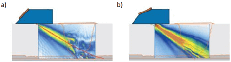
Figure 1.- Beam distortion a) Shear waves, b) Longitudinal waves
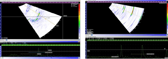
Figure 2.- Comparison of the signal-to-noise ratio (SNR) between the wave modes (a) Cut and (b) Longitudinally.
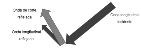
Figure 3.- Incidence and mode of conversion of the longitudinal wave in the posterior wall
Reference Patterns
In order to establish the level of sensitivity or gain of the test and validate the technique to be used, it is recommended to make use of replicas of the weld to be inspected and make holes inside them to establish the level of sensitivity for the use of waves. longitudinal, and notched at the root to simulate an open discontinuity in this part of the joint and thereby establish the level of sensitivity for the use of shear waves. A design for a reference standard is shown in Figure 4.
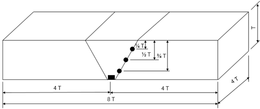
Figure 4.- Reference pattern model
Conclusions and recommendations
From the foregoing, the following is concluded and recommended:
- Shear waves suffer a marked greater attenuation than longitudinal waves, however the incidence of the latter in faults connected to the back surface is poor and invariable, so longitudinal waves are recommended for the evaluation of the interior volume of the weld. and shear waves for fault detection in the area adjacent to the root of the side from which the inspection is performed.
- Longitudinal waves undergo a mode change as they strike the back surface, where most of the energy is reflected as a shear wave. From the above, longitudinal wave inspection should be limited to mid-jump (1st leg) and it is recommended to flush the crown of the weld to assess the full interior volume of the joint.
- Better performance has been shown for dual probes and longitudinal waves (TR-L), linear or matrix array, the latter being preferable, so this type of transducer is recommended for the evaluation of the interior of the volume of the welded joint. .
- In order to establish the sensitivity levels (gain) of the transducers to be used and to demonstrate the reliability of the test to be carried out, reference standards must be used that are replicas of the joints to be evaluated with notches in the root and holes in the weld volume.
References
- The International Institute of Welding, “Handbook on the Ultrasonic Examination of Austenitic Welds”, 1985
- OECD Nuclear Energy Agency – CSNI Report No. 94 “The Ultrasonic Inspection of Austenitic Materials – State of the art report”, 1986
- François Lachance, Dominic Giguere and Philippe Rioux, Sonatest – Quebec, Paper “High Frequency Austenitic Stainless Steel Solution” – 15th Asia Pacific Conference for Non-Destructive Testing (APCNDT 2017), Singapore, 2017.
- Michael Moles and Sebastien Rigault, Olympus, Paper “Guidelines for Automated Ultrasonic Inspection Austenitic Welds”, 2020.

About the author: Carlos Álvarez, mechanical engineer by profession with 27 years of experience in the discipline of non-destructive testing, mainly in the oil and gas sector, with level III certification by the American society for non-destructive testing in the ultrasound method.