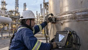
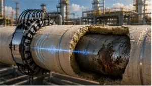
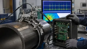
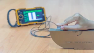
ASME Boiler and Pressure Vessel Code, Section V , Article 4 covers ultrasonic examination of welds when invoked by a referencing code section. . For encoded phased array inspection, Mandatory Appendix V provides the requirements for L-scan and S-scan linear scanning using linear array probes.
The overall process is familiar: plan the inspection, calibrate the system, collect data, evaluate indications, and document the examination. Within that workflow, ASME has some specific requirements for geometry, calibration blocks, scanning, and evaluation that are important when developing a PAUT setup.
1. Plan the Inspection
Appendix V requires a scan plan this works with the written procedure to define the examination. That includes the weld geometry, examination surfaces, probe and wedge, focal laws, scan direction, scanner configuration, and required coverage.
This is a good application for the XEO’s true-geometry rendering and 3D ray tracing. The part, weld, wedge, and sound paths can be viewed together while the scan plan is being built, making the effect of curvature and probe position easier to see before scanning.

The same process can be used for both longitudinal and circumferential welds, but component curvature can have a significant effect on the setup. For a longitudinal seam, as shown in Figure 1, the scanner travels along the vessel or pipe axis; for a circumferential weld, it travels around the component.
ASME also addresses the physical fit of the search unit on curved surfaces. When contouring is required, Article 4 limits the extent to which the wedge contour can vary from the actual component diameter. For OD scanning, the wedge contour diameter must be equal to or larger than the component OD, but only by a limited amount: up to 1 in. [25 mm] larger for components under 4 in. diameter, up to 2 in. [50 mm] larger for components from 4 to 10 in., and up to 4 in. [100 mm] larger for components over 10 in. For ID scanning, the contour diameter must be equal to or smaller than the component ID, with the same limits applied in the opposite direction.
.
2. Match the calibration to the application
Calibration block requirements are one of the more application-specific parts of Article 4.
For examination surfaces 20 in. [500 mm] diameter and smaller, the basic calibration block
must be curved. A single curved block can be used over a component-diameter range of 0.9 to
1.5 times the block diameter. An 8 in. diameter block, for example, can cover components
from 7.2 to 12 in. diameter.
ASME also distinguishes between piping and non-piping calibration blocks.
The standard piping block uses surface notches, while an alternate design may use side-drilled holes. Where notches are used, they are 8%T to 11%T deep, no more than 1/4 in. [6 mm] wide, and at least 1 in. [25 mm] long.

Figure 2 – Example ASME piping calibration block.
Non-piping blocks use a different arrangement of SDHs and surface notches, with reflector size and block thickness based on weld thickness.
Once the correct block is selected, Appendix V requires the beams used during the examination to be calibrated for distance and amplitude over the applicable sound paths.
With multiple scans and focal laws involved, the XEO Calibration Dashboard keeps the configured calibrations together in one status view. The element-check tool can apply predefined acceptance limits and retain the resulting probe status with the setup.

3. Collect the encoded data
Appendix V requires encoded linear scanning with the probe maintained at a constant stand off from the weld.
The scanning requirements include several specific limits:
- S-scan angular increments are limited to 1° maximum, or enough to provide at least 50% beam overlap.
- Multiple scan lines require at least 10% overlap.
- Data dropout must remain below two data lines per inch [25 mm], with no adjacent skipped lines.
- A-scan data is recorded unprocessed and without thresholding.
- The Maximum recording increment is 1 mm below 3 in. [75 mm] thickness and 2 mm at 3 in. [75 mm] and above.
During acquisition, the operator may only need an S-scan and C-scan to monitor coverage, coupling, encoder position, and indications. XEO layouts can be arranged around the inspection, keeping the acquisition screen relatively simple even when the underlying setup is more complex.

4. Evaluate what the data Is telling you
Article 4 requires indications exceeding 20% of the reference level to be investigated sufficiently to determine their nature and evaluate them against the acceptance criteria of the referencing code section. The 20% level is therefore an evaluation threshold, not automatically a rejection level.
This distinction becomes important because Section V may be used with several different construction codes .
For example, ASME Section VIII, Division 1, Mandatory Appendix 12 and ASME B31.1 Power Piping use essentially the same workmanship-based ultrasonic acceptance criteria. Cracks, lack of fusion, and incomplete penetration are unacceptable regardless of length. Other discontinuities are unacceptable when they exceed the reference amplitude and their length exceeds:
- 1/4 in. [6 mm] for thicknesses up to 3/4 in. [19 mm]
- 1/3t for thicknesses over 3/4 in. through 2-1/4 in. [19–57 mm]
- 3/4 in. [19 mm] for thicknesses over 2-1/4 in. [57 mm]
ASME B31.3 Process Piping uses the same three amplitude and length limits, but its ultrasonic acceptance paragraph is written around linear-type discontinuities. This demonstrates that the referencing code must be checked rather than assuming that one ASME acceptance table applies universally.
Section V Article 4 also requires the inspector to distinguish actual flaws from responses caused by weld or component geometry. Encoded PAUT helps with that evaluation because the indication can be reviewed in relation to its position in the weld rather than judged only from a live A-scan.
On the XEO, the same encoded file acquired using a simple S-scan/C-scan layout can be rearranged during analysis to add A-, B-, C-, and S-scan views for a closer look at indication position, response, and length.

5. Document the examination
Article 4 requires the examination record to identify the equipment, calibration, weld or volume scanned, examination surfaces, restricted-access areas, and rejectable indications or cleared areas. Appendix V adds PAUT-specific details such as probe element size and pitch, focal-law parameters, wedge angle, instrument settings, and scan-plan variables.
With the XEO, the setup, calibration status, encoded data, and analysis remain together with the inspection file, making the final review and reporting process easier without having to reconstruct the setup after the scan
A better workflow, not a different inspection
ASME still defines the inspection: establish the correct coverage, calibrate the system, collect valid encoded data, evaluate the indications, and maintain the required records.
What has changed is how efficiently those steps can be completed.
3D scan planning, automatic element evaluation, centralized calibration status, customizable acquisition and analysis layouts, and guided inspection instructions allow the XEO to keep much of the instrument setup in the background so the operator can stay focused on the examination.
Advanced PAUT does not have to mean a complicated workflow.
Links: XEO, X2 Series Probes, STIX Scanner
Get in touch with your local Sonatest expert, available in more than 50 countries over 5 continents!
Contact: Sonatest (Head Office)
Dickens Road, Old Wolverton Milton Keynes, MK12 5QQ
t: +44 (0)1908 316345
e: sales@sonatest.com Sonatest
(North America)
12775 Cogburn, San Antonio Texas, 78249
t: +1 (210) 697-0335
References
- American Society of Mechanical Engineers. (2021). Power piping (ASME Code B31.1-2020). ASME.
- American Society of Mechanical Engineers. (2022). Process piping (ASME Code B31.3-2022). ASME.
- American Society of Mechanical Engineers. (2023a). ASME boiler and pressure vessel code, Section V: Nondestructive examination (Article 4 & Mandatory Appendix V). ASME.
- American Society of Mechanical Engineers. (2023b). ASME boiler and pressure vessel code, Section VIII, Division 1: Rules for construction of pressure vessels (Mandatory Appendix 12). ASME.